We wanted to design a manipulator to attendance the IRB 1400 robot in different operations it can execute. In principle, it has the role of extracting from the buffers parallelepiped and cylinder pieces (pins). Once the pieces are extracted, the robot grabs them, in order to effectuate different operations: palletizing (pins or parallelepipeds), assembling or welding simulation (line or point welding). The set of operations may be diversified on user’s wish.
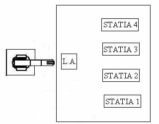
The principle scheme of this manipulator is as follows:
Stations 1 and 2 are extracting parallelepiped pieces, station 3 thick pins, and station 4 thin pins. The piece holders capacity corresponding to stations 1, 2 and 3 is of eight elements, the fourth having a double capacity. L.A. represent the place where the robot can execute the assembling operations.
Execution elements are represented by SMC pneumatic pistons. They are using, in order to function, compressed air furnished by an alternative compressor with piston, who is capable of assure a pressure of about 8 bar.
On installation input (manipulator) the air must have certain parameters for reliable functioning. Thus, the air pressure regulation, air filtering and lubricating are realized by the FRL group (Filter, Regulator and Lubricator). The next pneumatic element is a manual action blast-control valve for air admission into installation.
A control of manipulator function safety is wanted too, so the next element is an electro-valve, who, through pressing of an alarm button, it will purge into atmosphere the air under pressure from the installation. Then follows four grouped two-by-two electro-valves, who will distribute the air to the pneumatic pistons. Before entering into the electro-valves, the air pass by two pneumatic resistors (each one for a group of two electro-valves) for controlling the advance and retreat speeds of the pistons.
Piston positions (advanced / retreated) is known because of two proximity sensors placed on every four pistons, at their end strokes. Also, the parallelepiped presence into piece holders is detected by two mini- contacts, one for each piece holder.
It must be well known the fact that whole range of actuator elements, distribution and detection are SMC™ brand.
Pneumatic diagram of the manipulator is:
Technical features of pneumatic elements are:
FRL group (1)
- Pressure regulator + air filter EAW200
air pressure range: 0.5--8.5bar;
- Lubricator EAL2000
Maximum pressure on function: 9.9bar;
Admission valve (2) EVHS400
3/2 manual valve;
Normal closed;
Pressure range supported;
Safety valve (3) EVZ512
3/2 electro-valve with manual pilot;
Normal closed;
Pneumatic resistors (4, 5) AS2000-FO1
Piston command valves (7, 8, 11, 12) 2VZ5220-5MZ-01F
5/2 electro-valve with manual pilot and separate discharges;
Pneumatic pistons (6, 9, 10, 13) C82ADAB85-150
double effect pneumatic piston with controlled air-friction damper;
rod stroke 150mm;
maximum function pressure 10bar;
The parallelepipeds extracting stations have the following structure:
Parallelepiped Extractor
1. pneumatic pistons;
2. pusher;
3. piece holder;
4. micro-contact who detects the presence of the piece;
5. stand used by the pusher.
The pin extracting station structure is the following:
Pin extractor
1. pneumatic piston;
2. pin carrier;
3. piece holder.
1) parallelepiped grab area
His actuation is made by an double effect pneumatic piston, the air being distributed by a 5/2 electro-valve with automated pilot and separated discharges. Gripper pneumatic diagram is as shown:
Robot interconnection with the manipulator is made by controller input/output port. His indicator is DSQC 327, being digital inputs/outputs. There are two slots of 8 inputs each and two slots of 8 outputs. The power needed to function in the I/O ports logic is a source of 24V cc.
I/O activation diagrams are:

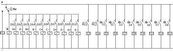
I13 is the input who is activated when alarm button is pressed. It is a condition for the running program to stop until the alarm button is released.
I3 and I4 represent the inputs associated to micro-contacts who determine the presence of pieces into piece holders 1 and 2. When the piece holders are empty, the work cycle is stopped until they are feed again.
I5, I6, I7, I8, I9, I10, I11 and I12 symbolize the inputs who are activated by sensors placed on pneumatic pistons. They are conditions too for the work cycle to complete.
A+, A- are the electro-valve command coils for station 1 piston air distribution. Identically, B+, B- are associated to station 2 piston, C+, C- to station 3 piston and D+, D- to station 4 piston. E+ and E- have a role in gripper closing and opening.
X is the command coil of the electro-valve who make the air exhaust into atmosphere in emergency cases.
D01, D03, D05, and D07 are the outputs who, by program activation, give the advance command to the four pistons. D02, D04, D06 and D08 give the retreat command to the pistons.
D09 and D10, through activation, open or close the gripper.
MC1 and MC2 represent micro-contacts who detects piece presence into piece holders 1 and 2.
S1, S2, S3, S4, S5, S6, S7 and S8 symbolize the sensors placed on the four pneumatic pistons on their stroke ends. So, it is well known their position (advanced/retreated). This feature is important in manipulator cycle management.