| |
Instructions |
TriggIO Defines a fixed position I/O event
TriggIO
is used to define conditions and actions for setting a digital, a group of digital,or an analog output signal at a fixed position along the robot’s movement path.To obtain a fixed position I/O event, TriggIO compensates for the lag in the control system (lag between robot and servo) but not for any lag in the external equipment. For compensation of both lags use TriggEquip. The data defined is used for implementation in one or more subsequent TriggL, TriggC or TriggJ instructions.Examples
VAR triggdata gunon;
TriggIO gunon, 10 \DOp:=gun, 1;
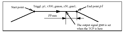
TriggL p1, v500, gunon, z50, gun1;
The digital output signal
gun is set to the value 1 when the TCP is 10 mm before the point p1.
Arguments
TriggIO TriggData Distance [ \Start ] | [ \Time ]
[ \DOp ] | [ \GOp ] | [\AOp ] | [\ProcID ] SetValue
[ \DODelay ]
TriggData
Data type: triggdataVariable for storing the
triggdata returned from this instruction. These triggdata are then used in the subsequent TriggL, TriggC or TriggJ instructions.Distance
Data type: numDefines the position on the path where the I/O event shall occur. Specified as the distance in mm (positive value) from the end point of the movement path (applicable if the argument \
Start or \Time is not set). See the section entitled Program execution for further details.[ \Start ]
Data type: switchUsed when the distance for the argument
Distance starts at the movement start point instead of the end point.[ \Time ]
Data type: switchUsed when the value specified for the argument
Distance is in fact a time in seconds (positive value) instead of a distance. Fixed position I/O in time can only be used for short times (< 0.5 s) before the robot reaches the end point of the instruction. See the section entitled Limitations for more details.[ \DOp ]
(Digital OutPut) Data type: signaldoThe name of the signal, when a digital output signal shall be changed.
[ \GOp ]
(Group OutPut) Data type: signalgoThe name of the signal, when a group of digital output signals shall be changed.
[ \AOp ]
(Analog Output) Data type: signalaoThe name of the signal, when a analog output signal shall be changed.
[ \ProcID]
(Process Identity) Data type: numNot implemented for customer use.(The identity of the IPM process to receive the event. The selector is specified in the argument
SetValue.)SetValue
Data type: numDesired value of output signal (within the allowed range for the current signal).
[ \DODelay]
(Digital Output Delay) Data type: numTime delay in seconds (positive value) for a digital output signal or group of digital output signals. Only used to delay setting digital output signals, after the robot has reached the
specified position. There will be no delay if the argument is omitted. The delay is not synchronised with the movement.Program execution
When running the instruction
TriggIO, the trigger condition is stored in a specified variable for the argument TriggData. Afterwards, when one of the instructions TriggL, TriggC or TriggJ is executed, the following are applicable, with regard to the definitions in TriggIO: The distance specified in the argument Distance:Linear movement The straight line distance
Circular movement The circle arc length
Non-linear movement The approximate arc length along the path (to obtain adequate accuracy, the distance should not exceed one half of the arc length).
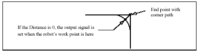
The fixed position I/O will be generated when the start point (end point) is passed, if the specified distance from the end point (start point) is not within the length of movement of the current instruction (
Trigg...).Examples
VAR triggdata glueflow;
TriggIO glueflow, 1 \Start \AOp:=glue, 5.3;
MoveJ p1, v1000, z50, tool1;
TriggL p2, v500, glueflow, z50, tool1;
The analog output signal
glue is set to the value 5.3 when the work point passes a point located 1 mm after the start point p1....
TriggL p3, v500, glueflow, z50, tool1;
The analog output signal
glue is set once more to the value 5.3 when the work point passes a point located 1 mm after the start point p2.Limitations
I/O events with distance (without the argument \
Time) is intended for flying points (corner path). I/O events with distance, using stop points, results in worse accuracy than specified below. I/O events with time (with the argument \Time) is intended for stop points. I/O events with time, using flying points, results in worse accuracy than specified below. I/O events with time can only be specified from the end point of the movement. This time cannot exceed the current braking time of the robot, which is max. approx. 0.5 s (typical values at speed 500 mm/s for IRB2400 150 ms and for IRB6400 250 ms). If the specified time is greater that the current braking time, the event will be generated anyhow, but not until braking is started (later than specified). However, the whole of the movement time for the current movement can be utilised during small and fast movements.Typical absolute accuracy values for set of digital outputs +/- 5 ms.
Typical repeat accuracy values for set of digital outputs +/- 2 ms.
Syntax
TriggIO
[ TriggData ’:=’ ] < variable (
VAR) of triggdata> ‘,’[ Distance ’:=’ ] < expression (
IN) of num>[ ’\’ Start ] | [ ’\’ Time ]
[ ’\’ DOp ’:=’ < variable (
VAR) of signaldo> ]| [ ’\’ GOp ’:=’ < variable (
VAR) of signalgo> ]| [ ’\’ AOp ’:=’ < variable (
VAR) of signalao> ]| [ ’\’ ProcID ’:=’ < expression (
IN) of num> ] ‘,’[ SetValue ’:=’ ] < expression (
IN) of num>[ ’\’ DODelay ’:=’ < expression (
IN) of num> ] ‘;’
TriggJ Axis-wise robot movements with events
TriggJ (Trigg Joint)
is used to set output signals and/or run interrupt routines at fixed positions, at the same time as the robot is moving on a circular path. One or more (max. 4) events can be defined using the instructions TriggIO, TriggEquip or TriggInt and afterwards these definitions are referred to in the instruction TriggJ.Examples
VAR triggdata gunon;
TriggIO gunon, 0 \Start \DOp:=gun, on;
MoveL p1, v500, z50, gun1;
TriggJ p2, v500, gunon, fine, gun1;
The digital output signal
gun is set when the robot’s TCP passes the midpoint ofthe corner path of the point
p1.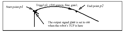
System Data Types and Routines 2-TriggJ-415
Example of fixed-position IO event.
Arguments
TriggJ [\Conc] ToPoint Speed [ \T ] Trigg_1 [ \T2 ] [ \T3 ] [ \T4 ]
Zone Tool [ \WObj ]
[ \Conc ]
(Concurrent) Data type: switchSubsequent instructions are executed at once. This argument is used to shorten the cycle time when, for example, communicating with external equipment, if synchronisation is not required. It can also be used to tune the execution of the robot path, to avoid warning 50024 Corner path failure or error 40082 Deceleration limit. Using the argument \Conc, the number of movement instructions in succession is limited to 5. In a program section that includes StorePath-RestoPath, movement instructions with the argument \Conc are not permitted. If this argument is omitted and the ToPoint is not a stop point, the subsequent instruction is executed some time before the robot has reached the programmed zone .
ToPoint
Data type: robtargetThe destination point of the robot and external axes. It is defined as a named position or stored directly in the instruction (marked with an * in the instruction).
Speed Data type: speeddata
The speed data that applies to movements. Speed data defines the velocity of the tool centre point, the external axes and of the tool reorientation.
[ \T ]
(Time) Data type: numThis argument is used to specify the total time in seconds during which the robot moves. It is then substituted for the corresponding speed data.
Trigg_1
Data type: triggdataVariable that refers to trigger conditions and trigger activity, defined earlier in the program using the instructions
TriggIO, TriggEquip or TriggInt.[ \T2]
(Trigg 2) Data type: triggdataVariable that refers to trigger conditions and trigger activity, defined earlier in the program using the instructions
TriggIO, TriggEquip or TriggInt.[ \T3 ]
(Trigg 3) Data type: triggdataVariable that refers to trigger conditions and trigger activity, defined earlier in the program using the instructions
TriggIO, TriggEquip or TriggInt.[ \T4 ]
(Trigg 4) Data type: triggdataVariable that refers to trigger conditions and trigger activity, defined earlier in the program using the instructions
TriggIO, TriggEquip or TriggInt.Zone
Data type: zonedataZone data for the movement. Zone data describes the size of the generated corne path.
Tool
Data type: tooldataThe tool in use when the robot moves. The tool centre point is the point that is moved to the specified destination position.
[ \WObj]
(Work Object) Data type: wobjdataThe work object (coordinate system) to which the robot position in the instruction is related.
This argument can be omitted, and if it is, the position is related to the world coordinate system. If, on the other hand, a stationary TCP or coordinated external axes are used, this argument must be specified for a linear movement relative to the work object to be performed.
Program execution
See the instruction
MoveJ for information about joint movement. As the trigger conditions are fulfilled when the robot is positioned closer and closer to the end point, the defined trigger activities are carried out. The trigger conditions are fulfilled either at a certain distance before the end point of the instruction, or at a certain distance after the start point of the instruction, or at a certain point in time (limited to a short time) before the end point of the instruction. During stepping execution forwards, the I/O activities are carried out but the interrupt routines are not run. During stepping execution backwards, no trigger activities at all are carried out.Examples
VAR intnum intno1;
VAR triggdata trigg1;
...
CONNECT intno1 WITH trap1;
TriggInt trigg1, 0.1 \Time , intno1;
...
TriggJ p1, v500, trigg1, fine, gun1;
TriggJ p2, v500, trigg1, fine, gun1;
...
IDelete intno1;
The interrupt routine
trap1 is run when the work point is at a position 0.1 s before the point p1 or p2 respectively.Limitations
If the current start point deviates from the usual, so that the total positioning length of the instruction
TriggJ is shorter than usual (e.g. at the start of TriggJ with the robot position at the end point), it may happen that several or all of the trigger conditions are fulfilled immediately and at the same position. In such cases, the sequence in which the trigger activities are carried will be undefined. The program logic in the user program may not be based on a normal sequences of trigger activities for an "incomplete movement".Syntax
TriggJ
[’\’ Conc ’,’]
[ ToPoint ’:=’ ] < expression (
IN) of robtarget > ’,’[ Speed ’:=’ ] < expression (
IN) of speeddata >[ ’\’ T ’:=’ < expression (
IN) of num > ] ’,’[Trigg_1 ’:=’ ] < variable (
VAR) of triggdata >[ ’\’ T2 ’:=’ < variable (
VAR) of triggdata > ][ ’\’ T3 ’:=’ < variable (
VAR) of triggdata > ][ ’\’ T4 ’:=’ < variable (
VAR) of triggdata > ] ‘,’[Zone ’:=’ ] < expression (
IN) of zonedata > ‘,’[ Tool ’:=’ ] < persistent (
PERS) of tooldata >[ ’\’ WObj ’:=’ < persistent (
PERS) of wobjdata > ] ’;’TriggL Linear robot movements with events
TriggL (Trigg Linear)
is used to set output signals and/or run interrupt routines at fixed positions, at the same time as the robot is making a linear movement. One or more (max. 4) events can be defined using the instructions TriggIO, TriggEquip or TriggInt and afterwards these definitions are referred to in the instruction TriggL.Examples
VAR triggdata gunon;
TriggIO gunon, 0 \Start \DOp:=gun, on;
MoveJ p1, v500, z50, gun1;
TriggL p2, v500, gunon, fine, gun1;
The digital output signal
gun is set when the robot’s TCP passes the midpoint of the corner path of the point p1.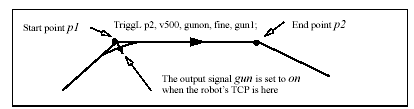
System Data Types and Routines 2-TriggL-419
Example of fixed-position IO event.
Arguments
TriggL [\Conc] ToPoint Speed [ \T ] Trigg_1 [ \T2 ] [ \T3 ] [ \T4 ]
Zone Tool [ \WObj ] [ \Corr ]
[ \Conc ]
(Concurrent) Data type: switchSubsequent instructions are executed at once. This argument is used to shorten the cycle time when, for example, communicating with external equipment, if synchronisation is not required. It can also be used to tune the execution of the robot path, to avoid warning 50024 Corner path failure or error 40082 Deceleration limit. Using the argument \Conc, the number of movement instructions in succession is limited to 5. In a program section that includes StorePath-RestoPath, movement instructions with the argument \Conc are not permitted. If this argument is omitted and the ToPoint is not a stop point, the subsequent instruction is executed some time before the robot has reached the programmed zone.
ToPoint
Data type: robtargetThe destination point of the robot and external axes. It is defined as a named position or stored directly in the instruction (marked with an * in the instruction).
Speed Data type: speeddata
The speed data that applies to movements. Speed data defines the velocity of the tool centre point, the external axes and of the tool reorientation.
[ \T ]
(Time) Data type: numThis argument is used to specify the total time in seconds during which the robot moves. It is then substituted for the corresponding speed data.
Trigg_1
Data type: triggdataVariable that refers to trigger conditions and trigger activity, defined earlier in the program using the instructions
TriggIO, TriggEquip or TriggInt.[ \T2]
(Trigg 2) Data type: triggdataVariable that refers to trigger conditions and trigger activity, defined earlier in the program using the instructions
TriggIO, TriggEquip or TriggInt.[ \T3 ]
(Trigg 3) Data type: triggdataVariable that refers to trigger conditions and trigger activity, defined earlier in the program using the instructions
TriggIO, TriggEquip or TriggInt.[ \T4 ]
(Trigg 4) Data type: triggdataVariable that refers to trigger conditions and trigger activity, defined earlier in the program using the instructions
TriggIO, TriggEquip or TriggInt.Zone
Data type: zonedataZone data for the movement. Zone data describes the size of the generated corner path.
Tool
Data type: tooldataThe tool in use when the robot moves. The tool centre point is the point that is moved to the specified destination position.
[ \WObj]
(Work Object) Data type: wobjdataThe work object (coordinate system) to which the robot position in the instruction is related.
This argument can be omitted, and if it is, the position is related to the world coordinate system. If, on the other hand, a stationary TCP or coordinated external axes are used, this argument must be specified for a linear movement relative to the work object to be performed.
[ \Corr]
(Correction) Data type: switchCorrection data written to a corrections entry by the instruction
CorrWrite will be added to the path and destination position, if this argument is present.Program execution
See the instruction
MoveL for information about linear movement. As the trigger conditions are fulfilled when the robot is positioned closer and closer to the end point, the defined trigger activities are carried out. The trigger conditions are fulfilled either at a certain distance before the end point of the instruction, or at a certain distance after the start point of the instruction, or at a certain point in time (limited to a short time) before the end point of the instruction. During stepping execution forwards, the I/O activities are carried out but the interrupt routines are not run. During stepping execution backwards, no trigger activities at all are carried out.Examples
VAR intnum intno1;
VAR triggdata trigg1;
...
CONNECT intno1 WITH trap1;
TriggInt trigg1, 0.1 \Time, intno1;
...
TriggL p1, v500, trigg1, fine, gun1;
TriggL p2, v500, trigg1, fine, gun1;
...
IDelete intno1;
The interrupt routine
trap1 is run when the work point is at a position0.1
s before the point p1 or p2 respectively.Limitations
If the current start point deviates from the usual, so that the total positioning length of the instruction
TriggL is shorter than usual (e.g. at the start of TriggL with the robot position at the end point), it may happen that several or all of the trigger conditions are fulfilled immediately and at the same position. In such cases, the sequence in which the trigger activities are carried out will be undefined. The program logic in the user program may not be based on a normal sequence of trigger activities for an "incomplete movement".Syntax
TriggL
[’\’ Conc ’,’]
[ ToPoint ’:=’ ] < expression (
IN) of robtarget > ’,’[ Speed ’:=’ ] < expression (
IN) of speeddata >[ ’\’ T ’:=’ < expression (
IN) of num > ] ’,’[Trigg_1 ’:=’ ] < variable (
VAR) of triggdata >[ ’\’ T2 ’:=’ < variable (
VAR) of triggdata > ][ ’\’ T3 ’:=’ < variable (
VAR) of triggdata > ][ ’\’ T4 ’:=’ < variable (
VAR) of triggdata > ] ‘,’[Zone ’:=’ ] < expression (
IN) of zonedata > ‘,’[ Tool ’:=’ ] < persistent (
PERS) of tooldata >[ ’\’ WObj ’:=’ < persistent (
PERS) of wobjdata > ][ ’\’ Corr ]’;’
TRYNEXT Jumps over an instruction which has caused an error
TRYNEXT
is used to jump over an instruction which has caused an error. Instead, the next instruction is run.Example
reg2 := reg3/reg4;
.ERROR
IF ERRNO = ERR_DIVZERO THEN
reg2:=0;
TRYNEXT;
ENDIF
An attempt is made to divide
reg3 by reg4. If reg4 is equal to 0 (division by zero), a jump is made to the error handler, where reg2 is set to 0. The TRYNEXT instruction is then used to continue with the next instruction.Program execution
Program execution continues with the instruction subsequent to the instruction that caused the error.
Limitations
The instruction can only exist in a routine’s error handler.
Syntax
TRYNEXT
’;’
TuneReset Resetting servo tuning
TuneReset
is used to reset the dynamic behaviour of all robot axes and external mechanical units to their normal values.Example
TuneReset;
Resetting tuning values for all axes to 100%.
Program execution
The tuning values for all axes are reset to 100%. The default servo tuning values for all axes are automatically set by executing instruction
TuneReset- at a cold start-up
- when a new program is loaded
- when starting program execution from the beginning.
Syntax
TuneReset ’;’
TuneServo Tuning servos
TuneServo
is used to tune the dynamic behaviour of separate axes on the robot. It is not necessary to use TuneServo under normal circumstances, but sometimes tuning can be optimised depending on the robot configuration and the load characteristics. For external axes TuneServo can be used for load adaptation.Incorrect use of the
TuneServo can cause oscillating movements or torques that can damage the robot. You must bear this in mind and be careful when using the TuneServo. Avoid doing TuneServo commands at the same time as the robot is moving. It can result in momentary high CPU loads causing error indication and stops. Note. To obtain optimal tuning it is essential that the correct load data is used.Check on this before using
TuneServo. Generally, optimal tuning values often differ between different robots. Optimal tuning may also change with time.Improving path accuracy
For robots running at lower speeds, TuneServo can be used to improve the path accuracy by:
- Tuning tune_kv and tune_ti (see the tune types description below).
- Tuning friction compensation parameters (see below).
These two methods can be combined.
Other possibilities to improve the path accuracy:
- Decreasing path resolution can improve the path. Note: a value of path resolution which is too low will cause CPU load problems.
- The accuracy of straight lines can be improved by decreasing acceleration using
AccSet. Example: AccSet 20, 10.
Description
Tune_df
Tune_df is used for reducing overshoots or oscillations along the path. There is always an optimum tuning value that can vary depending on position and movement length. This optimum value can be found by changing the tuning in small steps (1 - 2%) on the axes that are involved in this unwanted behaviour. Normally the optimal tuning will be found in the range 70% - 130%. Too low or too high tuning values have a negative effect and will impair movements considerably. When the tuning value at the start point of a long movement differs considerably from the tuning value at the end point, it can be advantageous in some cases to use an intermediate point with a corner zone to define where the tuning value will change. Some examples of the use of
TuneServo to optimise tuning follow below: IRB 6400, in a press service application (extended and flexible load), axes 4 - 6:Reduce the tuning value for the current wrist axis until the movement is acceptable. A
change in the movement will not be noticeable until the optimum value is approached.
A low value will impair the movement considerably. Typical tuning value 25%.
IRB 6400, upper parts of working area. Axis 1 can often be optimised with a tuning value of 85% - 95%.
IRB 6400, short movement (< 80 mm). Axis 1 can often be optimised with a tuning value of 94% - 98%.
IRB 2400, with track motion. In some cases axes 2 - 3 can be optimised with a tuning value of 110% - 130%. The movement along the track can require a different tuning value compared with movement at right angles to the track. Overshoots and oscillations can be reduced by decreasing the acceleration or the acceleration ramp (AccSet), which will however increase the cycle time. This is an alternative method to the use of TuneServo.
Tune_dg
Tune_dg can reduce overshoots on rare occasions. Normally it should not be used.
Tune_df should always be tried first in cases of overshoots.
Tuning of tune_dg can be performed with large steps in tune value (eg. 50%, 100%, 200%, 400%).
Never use tune_dg when the robot is moving.
Tune_dh
Tune_dh can be used for reducing vibrations and overshoots (eg. large flexible load).
Tune value must always be lower than 100. Tune_dh increases path deviation and normally also increases cycle time.
Example:
IRB6400 with large flexible load which vibrates when the robot has stopped. Use tune_dh with tune value 15.
Tune_dh should only be executed for one axis. All axes in the same mechanical unit automatically get the same tune_value.Never use tune_dh when the robot is moving.
Tune_di
Tune_di can be used for reducing path deviation at high speeds.
A tune value in the range 50 - 80 is recommended for reducing path deviation.
Overshoots can increase (lower tune value means larger overshoot).
A higher tune value than 100 can reduce overshoot (but increases path deviation at high speed).
Tune_di should only be executed for one axis. All axes in the same mechanical unit automatically get the same tune_value.
Tune_dk
For future use.
Tune_kp, tune_kv, tune_ti external axes
These tune types affect position control gain (kp), speed control gain (kv) and speed control integration time (ti) for external axes. These are used for adapting external axes to different load inertias. Basic tuning of external axes can also be simplified by using these tune types.
Tune_kp, tune_kv, tune_ti robot axes
For robot axes, these tune types have another significance and can be used for reducing path errors at low speeds (< 500 mm/s). Recommended values: tune_kv 100 - 180%, tune_ti 50 - 100%. Tune_kp should not be used for robot axes. Values of tune_kv/tune_ti which are too high or too low will cause vibrations or oscillations. Be careful if trying to exceed these recommended values. Make changes in small steps and avoid oscillating motors.
Always tune one axis at a time
. Change the tuning values in small steps. Try to improve the path where this specific axis changes its direction of movement or where it accelerates or deccelerates. Never use these tune types at high speeds or when the required path accuracy is fulfilled.Friction compensation: tune_fric_lev and tune_fric_ramp
These tune types can be used to reduce robot path errors caused by friction and backlash at low speeds (10 - 200 mm/s). These path errors appear when a robot axis changes direction of movement. Activate friction compensation for an axis by setting the system parameter
Friction ffw on to TRUE (topic: Manipulator, type: Control parameters). The friction model is a constant level with opposite sign of the axis speed direction. Friction ffw level (Nm) is the absolute friction level at (low) speeds and is greater thanFriction ffw ramp (rad/s) (see figure)
.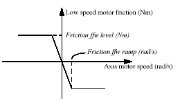
Friction model
Tune_fric_lev overrides the value of the system parameter
Friction ffw level. Tuning Friction ffw level (using tune_fric_lev) for each robot axis can improve the robots path accuracy considerably in the speed range 20 - 100 mm/s. For larger robots (especially the IRB6400 family) the effect will however be minimal as other sources of tracking errors dominate these robots. Tune_fric_ramp overrides the value of the system parameter Friction ffw ramp. In most cases there is no need to tune the Friction ffw ramp. The default setting will be appropriate.Tune one axis at a time
. Change the tuning value in small steps and find the level that minimises the robot path error at positions on the path where this specific axis changes direction of movement. Repeat the same procedure for the next axis etc. The final tuning values can be transferred to the system parameters.Example:
Friction ffw level = 1. Final tune value (tune_fric_lev) = 150%.
Set Friction ffw level = 1.5 and tune value = 100% (default value) which is
equivalent.
Arguments
TuneServo MecUnit Axis TuneValue [\Type]
MecUnit
(Mechanical Unit) Data type: mecunitThe name of the mechanical unit.
Axis
Data type: numThe number of the current axis for the mechanical unit (1 - 6).
TuneValue
Data type: numTuning value in percent (1 - 500). 100% is the normal value.
[\Type]
Data type: tunetypeType of servo tuning. Available types are
TUNE_DF, TUNE_KP, TUNE_KV,TUNE_TI
, TUNE_FRIC_LEV, TUNE_FRIC_RAMP, TUNE_DG, TUNE_DH,TUNE_DI
and TUNE_DK. These types are predefined in the system withconstants.
This argument can be omitted when using tuning type
TUNE_DF.Example
TuneServo MHA160R1, 1, 110 \Type:= TUNE_KP;
Activating of tuning type
TUNE_KP with the tuning value 110% on axis 1 in themechanical unit
MHA160R1.Program execution
The specified tuning type and tuning value are activated for the specified axis. This value is applicable for all movements until a new value is programmed for the current axis, or until the tuning types and values for all axes are reset using the instruction
TuneReset.The default servo tuning values for all axes are automatically set by executing instruction TuneReset- at a cold start-up
- when a new program is loaded
- when starting program execution from the beginning.
Limitations
Any active servo tuning are always set to default values at power fail. This limitation can be handled in the user program at restart after power failure.
Syntax
TuneServo
[MecUnit ’:=’ ] < variable (
VAR) of mecunit> ’,’[Axis ’:=’ ] < expression (
IN) of num> ’,’[TuneValue ’:=’ ] < expression (
IN) of num>[’\’ Type ’:=’ <expression (
IN) of tunetype>]’;’
UnLoad UnLoad a program module during execution
UnLoad
is used to unload a program module from the program memory during execution. The program module must previously have been loaded into the program memory using the instruction Load or StartLoad - WaitLoad.Example
UnLoad ram1disk \File:="PART_A.MOD";
UnLoad
the program module PART_A.MOD from the program memory, that previously was loaded into the program memory with Load. (See instructions Load). (ram1disk is a predefined string constant "ram1disk:").Arguments
UnLoad [\Save] FilePath [\File]
[\Save]
Data type: switchIf this argument is used, the program module is saved before the unloading starts. The program module will be saved at the original place specified in the
Load or StartLoad instruction.FilePath
Data type: stringThe file path and the file name to the file that will be unloaded from the program memory. The file path and the file name must be the same as in the previously executed
Load or StartLoad instruction. The file name shall be excluded when the argument \File is used.[\File]
Data type: stringWhen the file name is excluded in the argument
FilePath, then it must be defined with this argument. The file name must be the same as in the previously executed Load or StartLoad instruction.Program execution
To be able to execute an
UnLoad instruction in the program, a Load or StartLoad - WaitLoad instruction with the same file path and name must have been executed earlier in the program. The program execution waits for the program module to finish unloading before the execution proceeds with the next instruction After that the program module is unloaded and the rest of the program modules will be linked. For more information see the instructions Load or StartLoad-Waitload.Examples
UnLoad "ram1disk:DOORDIR/DOOR1.MOD";
UnLoad
the program module DOOR1.MOD from the program memory, that previously was loaded into the program memory with Load. UnLoad "ram1disk:" \File:="DOORDIR/DOOR1.MOD";Same as above but another syntax.
Unload \Save, "ram1disk:" \File:="DOORDIR/DOOR1.MOD";
Same as above but save the program module before unloading.
Limitations
It is not allowed to unload a program module that is executing. TRAP routines, system I/O events and other program tasks cannot execute during the unloading.Avoid ongoing robot movements during the unloading.Program stop during execution of
UnLoad instruction results in guard stop with motors off and error message "20025 Stop order timeout" on the Teach Pendant.Error handling
If the file in the
UnLoad instruction cannot be unloaded because of ongoing execution within the module or wrong path (module not loaded with Load or StartLoad), the system variable ERRNO is set to ERR_UNLOAD. This error can then be handled in the error handler.Syntax
UnLoad
[’
\’Save ’,’][FilePath’:=’]<expression (
IN) of string>[’
\’File’:=’ <expression (IN) of string>]’;’
WaitDI Waits until a digital input signal is set
WaitDI (Wait Digital Input)
is used to wait until a digital input is set.Example
WaitDI di4, 1;
Program execution continues only after the
di4 input has been set. WaitDI grip_status, 0;Program execution continues only after the
grip_status input has been reset.Arguments
WaitDI Signal Value [\MaxTime] [\TimeFlag]
Signal
Data type: signaldiThe name of the signal.
Value
Data type: dionumThe desired value of the signal.
[\MaxTime]
(Maximum Time) Data type: numThe maximum period of waiting time permitted, expressed in seconds. If this time runs out before the condition is met, the error handler will be called, if there is one, with the error code ERR_WAIT_MAXTIME. If there is no error handler, the execution will be stopped.
[\TimeFlag] (Timeout Flag) Data type: bool The output parameter that contains the value TRUE if the maximum permitted waiting time runs out before the condition is met. If this parameter is included in the instruction, it is not considered to be an error if the max. time runs out. This argument is ignored if the MaxTime argument is not included in the instruction.Program Running
If the value of the signal is correct, when the instruction is executed, the program simply continues with the following instruction. If the signal value is not correct, the robot enters a waiting state and when the signal changes to the correct value, the program continues. The change is detected with an interrupt, which gives a fast response (not polled). When the robot is waiting, the time is supervised, and if it exceeds the max time value, the program will continue if a Time Flag is specified, or raise an error if it’s not. If a Time Flag is specified, this will be set to true if the time is exceeded, otherwise it will be set to false.
Syntax
WaitDI
[ Signal ’:=’ ] < variable (
VAR) of signaldi > ’,’[ Value ’:=’ ] < expression (
IN) of dionum >[’\’MaxTime ’:=’<expression
(IN) of num>][’\’TimeFlag’:=’
<variable (VAR) of bool>] ’;’
WaitDO Waits until a digital output signal is set
WaitDO (Wait Digital Output)
is used to wait until a digital output is set.Example
WaitDO do4, 1;
Program execution continues only after the
do4 output has been set.WaitDO grip_status, 0;
Program execution continues only after the
grip_status output has been reset.Arguments
WaitDO Signal Value [\MaxTime] [\TimeFlag]
Signal
Data type: signaldoThe name of the signal.
Value
Data type: dionumThe desired value of the signal.
[\MaxTime]
(Maximum Time) Data type: numThe maximum period of waiting time permitted, expressed in seconds. If this time runs out before the condition is met, the error handler will be called, if there is one, with the error code ERR_WAIT_MAXTIME. If there is no error handler, the execution will be stopped.
[\TimeFlag]
(Timeout Flag) Data type: boolThe output parameter that contains the value TRUE if the maximum permitted waiting time runs out before the condition is met. If this parameter is included in the instruction, it is not considered to be an error if the max. time runs out. This argument is ignored if the
MaxTime argument is not included in the instruction.Program Running
If the value of the signal is correct, when the instruction is executed, the program simply continues with the following instruction. If the signal value is not correct, the robot enters a waiting state and when the signal changes to the correct value, the program continues. The change is detected with an interrupt, which gives a fast response (not polled). When the robot is waiting, the time is supervised, and if it exceeds the max time value, the program will continue if a Time Flag is specified, or raise an error if its not. If a Time Flag is specified, this will be set to true if the time is exceeded, otherwise it will be set to false.
Syntax
WaitDO
[ Signal ’:=’ ] < variable (
VAR) of signaldo > ’,’[ Value ’:=’ ] < expression (
IN) of dionum >[’\’MaxTime ’:=’<expression
(IN) of num>][’\’TimeFlag’:=’
<variable (VAR) of bool>] ’;’
WaitLoad Connect the loaded module to the task
WaitLoad
is used to connect the module, if loaded with StartLoad, to the program task. The loaded module must be connected to the program task with the instruction Wait- Load before any of its symbol/routines can be used. The loaded program module will be added to the modules already existing in the program memory. This instruction can also be combined with the function to unload some other program module, in order to minimise the number of links (1 instead of 2).Example
VAR loadsession load1;
...
StartLoad "ram1disk:PART_A.MOD", load1;
MoveL p10, v1000, z50, tool1 \WObj:=wobj1;
MoveL p20, v1000, z50, tool1 \WObj:=wobj1;
MoveL p30, v1000, z50, tool1 \WObj:=wobj1;
MoveL p40, v1000, z50, tool1 \WObj:=wobj1;
WaitLoad load1;
%"routine_x"%;
UnLoad "ram1disk:PART_A.MOD";
Load the program module PART_A.MOD from the
ram1disk into the program memory. In parallel, move the robot. Then connect the new program module to the program task and call the routine routine_x in the module PART_A.Arguments
WaitLoad [\UnloadPath] [\UnloadFile] LoadNo
[\UnloadPath]
Data type: stringThe file path and the file name to the file that will be unloaded from the program memory. The file name should be excluded when the argument
\UnloadFile is used.[\UnloadFile]
Data type: stringWhen the file name is excluded in the argument
\UnloadPath, then it must be defined with this argument.LoadNo
Data type: loadsessionThis is a reference to the load session, fetched by the instruction
StartLoad, to connect the loaded program module to the program task.Program execution
The instruction
WaitLoad will first wait for the loading to be completed, if it is not already done, and then it will be linked and initialised. The initialisation of the loaded module sets all variables at module level to their init values. Unsolved references will be accepted, if the system parameter for Tasks/BindRef is set to NO. However, when the program is started or the teach pendant function Program Window/File/Check Program is used, no check for unsolved references will be done if BindRef = NO. There will be a run time error on execution of an unsolved reference. Another way to use references to instructions, that are not in the task from the beginning, is to use Late Binding. This makes it possible to specify the routine to call with a string expression, quoted between two %%. In this case the BindRef parameter could be set to YES (default behaviour). The Late Binding way is preferable. To obtain a good program structure, that is easy to understand and maintain, all loading and unloading of program modules should be done from the main module, which is always present in the program memory during execution.Examples
StartLoad "ram1disk:DOORDIR/DOOR2.MOD", load1;
...
WaitLoad \UnloadPath:="ram1disk:DOORDIR/DOOR1.MOD", load1;
Load the program module
DOOR2.MOD from the ram1disk at the directoryDOORDIR
into the program memory and connect the new module to the task.The program module DOOR1.MOD will be unloaded from the program memory.
StartLoad "ram1disk:" \File:="DOORDIR/DOOR2.MOD", load1;
! The robot can do some other work
WaitLoad \UnloadPath:="ram1disk:" \File:= "DOORDIR/DOOR1.MOD", load1;
is the same as the instructions below but the robot can do some other work during the loading time and also do it faster (only one link).
Load "ram1disk:" \File:="DOORDIR/DOOR2.MOD";
UnLoad "ram1disk:" \File:="DOORDIR/DOOR1.MOD";
Error handling
If the file specified in the
StartLoad instruction cannot be found, the system variable ERRNO is set to ERR_FILNOTFND at execution of WaitLoad. If argument LoadNo refers to an unknown load session, the system variable ERRNO is set to ERR_UNKPROC. If the module is already loaded into the program memory, the system variable ERRNO is set to ERR_LOADED. The following errors can only occur when the argument \UnloadPath is used in the instruction WaitLoad:- If the program module specified in the argument \
UnloadPath cannot be unloaded because of ongoing execution within the module, the system variableERRNO is set to ERR_UNLOAD.
- If the program module specified in the argument \
UnloadPath cannot be unloaded because the program module is not loaded with Load or StartLoad-WaitLoad from the RAPID program, the system variable ERRNO is also set to ERR_UNLOAD. These errors can then be handled in the error handler.Syntax
WaitLoad
[ [ ’
\’ UnloadPath ’:=’ <expression (IN) of string> ][ ’
\’ UnloadFile ’:=’ <expression (IN) of string> ] ’,’ ][ LoadNo ’:=’ ] <variable (
VAR) of loadsession> ’;’
VelSet Changes the programmed velocity
VelSet
is used to increase or decrease the programmed velocity of all subsequent positioning instructions. This instruction is also used to maximize the velocity.Example
VelSet 50, 800;
All the programmed velocities are decreased to 50% of the value in the instruction. The TCP velocity is not, however, permitted to exceed 800 mm/s.
Arguments
VelSet Override Max
Override
Data type: numDesired velocity as a percentage of programmed velocity. 100% corresponds to the programmed velocity.
Max
Data type: numMaximum TCP velocity in mm/s.
Program execution
The programmed velocity of all subsequent positioning instructions is affected until a new
VelSet instruction is executed.The argument
Override affects:- All velocity components (TCP, orientation, rotating and linear external axes) in
speeddata
.- The programmed velocity override in the positioning instruction (the argument
\V).- Timed movements.
The argument
Override does not affect:- The welding speed in
welddata.- The heating and filling speed in
seamdata.The argument
Max only affects the velocity of the TCP.The default values for
Override and Max are 100% and 5000 mm/s respectively. These values are automatically set- at a cold start-up
- when a new program is loaded
- when starting program executing from the beginning.
Example
VelSet 50, 800;
MoveL p1, v1000, z10, tool1;
MoveL p2, v2000, z10, tool1;
MoveL p3, v1000\T:=5, z10, tool1;
The speed is
500 mm/s to point p1 and 800 mm/s to p2. It takes 10 seconds to move from p2 to p3.Limitations
The maximum speed is not taken into consideration when the time is specified in the
positioning instruction.
Syntax
VelSet
[ Override ’:=’ ] < expression (
IN) of num > ’,’[ Max ’:=’ ] < expression (
IN) of num > ’;’
WHILE Repeats as long as ...
WHILE
is used when a number of instructions are to be repeated as long as a given condition is met. If it is possible to determine the number of repetitions in advance, the FOR instruction can be used.Example
WHILE reg1 < reg2 DO
...
reg1 := reg1 +1;
ENDWHILE
Repeats the instructions in the WHILE loop as long as
reg1 < reg2.Arguments
WHILE Condition DO ... ENDWHILE
Condition
Data type: boolThe condition that must be met for the instructions in the WHILE loop to be executed.
Program execution
7. The condition is calculated. If the condition is not met, the WHILE loop terminates and program execution continues with the instruction following ENDWHILE.
8. The instructions in the WHILE loop are executed.
9. The WHILE loop is repeated, starting from point 1.
Syntax
(EBNF)
WHILE
<conditional expression> DO<instruction list>
ENDWHILE
Write Writes to a character-based file or serial channel
Write
is used to write to a character-based file or serial channel. The value of certain data can be written as well as text.Examples
Write logfile, "Execution started";
The text
Execution started is written to the file with reference name logfile.Write logfile, "No of produced parts="\Num:=reg1; The text No of produced parts=5, for example, is written to the file with the reference name logfile (assuming that the contents of reg1 is 5).Arguments
Write IODevice String [\Num] | [\Bool] | [\Pos] | [\Orient]
[\NoNewLine]
IODevice
Data type: iodevThe name (reference) of the current file or serial channel.
String
Data type: stringThe text to be written.
[\Num]
(Numeric) Data type: numThe data whose numeric values are to be written after the text string.
[\Bool]
(Boolean) Data type: boolThe data whose logical values are to be written after the text string.
[\Pos]
(Position) Data type: posThe data whose position is to be written after the text string.
[\Orient]
(Orientation) Data type: orientThe data whose orientation is to be written after the text string.
[\NoNewLine]
Data type: switchOmits the line-feed character that normally indicates the end of the text.
Program execution
The text string is written to a specified file or serial channel. If the argument
\NoNewLine is not used, a line-feed character (LF) is also written. If one of the arguments \Num, \Bool, \Pos or \Orient is used, its value is first converted to a text string before being added to the first string. The conversion from value to text string takes place as follows:Argument Value Text string
\Num 23 "23"
\Num 1.141367 "1.14137"
\Bool TRUE "TRUE"
\Pos [1817.3,905.17,879.11] "[1817.3,905.17,879.11]"
\Orient [0.96593,0,0.25882,0] "[0.96593,0,0.25882,0]"
The value is converted to a string with standard RAPID format. This means in principle 6 significant digits. If the decimal part is less than 0.000005 or greater than 0.999995, the number is rounded to an integer.
Example
VAR iodev printer;
.
Open "sio1:", printer\Write;
WHILE DInput(stopprod)=0 DO
produce_part;
Write printer, "Produced part="\Num:=reg1\NoNewLine;
Write printer, " "\NoNewLine;
Write printer, CTime();
ENDWHILE
Close printer;
A line, including the number of the produced part and the time, is output to a printer each cycle. The printer is connected to serial channel
sio1:. The printed message could look like this: Produced part=473 09:47:15Limitations
The arguments
\Num, \Bool, \Pos and \Orient are mutually exclusive and thus cannot be used simultaneously in the same instruction. This instruction can only be used for files or serial channels that have been opened for writing.Error handling
If an error occurs during writing, the system variable ERRNO is set to ERR_FILEACC. This error can then be handled in the error handler.
Syntax
Write
[IODevice’:=’] <variable
(VAR) of iodev>’,’[String’:=’] <expression
(IN) of string>[’\’Num’:=’
<expression (IN) of num> ]|
[’\’Bool’:=’ <expression (IN) of bool> ]|
[’\’Pos’:=’ <expression (IN) of pos> ]|
[’\’Orient’:=’ <expression (IN) of orient> ][’\’NoNewLine]’;’
WriteBin Writes to a binary serial channel
WriteBin
is used to write a number of bytes to a binary serial channel.Example
WriteBin channel2, text_buffer, 10;
10
characters from the text_buffer list are written to the channel referred to by channel2.Arguments
WriteBin IODevice Buffer NChar
IODevice
Data type: iodevName (reference) of the current serial channel.
Buffer
Data type: array of numThe list (array) containing the numbers (characters) to be written.
NChar
(Number of Characters) Data type: numThe number of characters to be written from the
Buffer.Program execution
The specified number of numbers (characters) in the list is written to the serial channel.
Limitations
This instruction can only be used for serial channels that have been opened for binary reading and writing.
Error handling
If an error occurs during writing, the system variable ERRNO is set to ERR_FILEACC. This error can then be handled in the error handler.
Example
VAR iodev channel;
VAR num out_buffer{20};
VAR num input;
VAR num nchar;
Open "sio1:", channel
\Bin;out_buffer{1} := 5; ( enq )
WriteBin channel, out_buffer, 1;
input := ReadBin (channel
\Time:= 0.1);IF input = 6 THEN ( ack )
out_buffer{1} := 2; ( stx )
out_buffer{2} := 72; ( ’H’ )
out_buffer{3} := 101; ( ’e’ )
out_buffer{4} := 108; ( ’l’ )
out_buffer{5} := 108; ( ’l’ )
out_buffer{6} := 111; ( ’o’ )
out_buffer{7} := 32; ( ’ ’ )
out_buffer{8} := StrToByte("w"\Char); ( ’w’ )
out_buffer{9} := StrToByte("o"\Char); ( ’o’ )
out_buffer{10} := StrToByte("r"\Char); ( ’r’ )
out_buffer{11} := StrToByte("l"\Char); ( ’l’ )
out_buffer{12} := StrToByte("d"\Char); ( ’d’ )
out_buffer{13} := 3; ( etx )
WriteBin channel, out_buffer, 13;
ENDIF
The text string
Hello world (with associated control characters) is written to a serial channel. The function StrToByte is used in the same cases to convert a string into a byte (num) data.Syntax
WriteBin
[
IODevice’:=’] <variable (VAR) of iodev>’,’[Buffer’:=’] <array {*} (
IN) of num>’,’[NChar’:=’] <expression (
IN) of num>’;’Related information
Described in:
Opening (etc.) of serial channels RAPID Summary -
CommunicationConvert a string to a byte data Functions -
StrToByteByte data Data Types -
byte
WriteAnyBin Writes data to a binary serial channel or file
WriteAnyBin (Write Any Binary)
is used to write any type of data to a binary serial channel or file.Example
VAR iodev channel2;
VAR orient quat1 := [1, 0, 0, 0];
...
Open "sio1:", channel2 \Bin;
WriteAnyBin channel2, quat1;
The
orient data quat1 is written to the channel referred to by channel2.Arguments
WriteAnyBin IODevice Data
IODevice
Data type: iodevThe name (reference) of the binary serial channel or file for the writing operation.
Data
Data type: ANYTYPEThe VAR or PERS containing the data to be written.
Program execution
As many bytes as required for the specified data are written to the specified binary serial channel or file.
Limitations
This instruction can only be used for serial channels or files that have been opened for binary writing.The data to be written by this instruction must have a
value data type of atomic, string, or record data type. Semi-value and non-value data types cannot be used. Array data cannot be used.Error handling
If an error occurs during writing, the system variable ERRNO is set to ERR_FILEACC.This error can then be handled in the error handler.
Example
VAR iodev channel;
VAR num input;
VAR robtarget cur_robt;
Open "sio1:", channel
\Bin;! Send the control character
enqWriteStrBin channel, "\05";
! Wait for the control character
ackinput := ReadBin (channel
\Time:= 0.1);IF input = 6 THEN
! Send current robot position
cur_robt := CRobT(\Tool:= tool1\WObj:= wobj1);
WriteAnyBin channel, cur_robt;
ENDIF
Close channel;
The current position of the robot is written to a binary serial channel.
Syntax
WriteAnyBin
[
IODevice’:=’] <variable (VAR) of iodev>’,’[Data’:=’] <var or pers (
INOUT) of ANYTYPE>’;’
WriteStrBin Writes a string to a binary serial channel
WriteStrBin (Write String Binary)
is used to write a string to a binary serial channel or binary file.Example
WriteStrBin channel2, "Hello World\0A";
The string
"Hello World\0A" is written to the channel referred to by channel2.The string is in this case ended with new line \0A. All characters and hexadecimal values written with WriteStrBin will be unchanged by the system.Arguments
WriteStrBin IODevice Str
IODevice
Data type: iodevName (reference) of the current serial channel.
Str
(String) Data type: stringThe text to be written.
Program execution
The text string is written to the specified serial channel or file.
Limitations
This instruction can only be used for serial channels or files that have been opened for binary reading and writing.
Error handling
If an error occurs during writing, the system variable ERRNO is set to ERR_FILEACC. This error can then be handled in the error handler.
Example
VAR iodev channel;
VAR num input;
Open "sio1:", channel
\Bin;! Send the control character
enqWriteStrBin channel, "\05";
! Wait for the control character
ackinput := ReadBin (channel
\Time:= 0.1);IF input = 6 THEN
! Send a text starting with control character
stx and ending with etxWriteStrBin channel, "\02Hello world\03";
ENDIF
Close channel;
The text string
Hello world (with associated control characters in hexadecimal) is written to a binary serial channel.Syntax
WriteStrBin
[
IODevice’:=’] <variable (VAR) of iodev>’,’[Str’:=’] <expression (
IN) of string>’;’
WaitTime Waits a given amount of time
WaitTime
is used to wait a given amount of time. This instruction can also be used to wait until the robot and external axes have come to a standstill.Example
WaitTime 0.5;
Program execution waits 0.5 seconds.
Arguments
WaitTime [\InPos] Time
[\InPos]
Data type: switchIf this argument is used, the robot and external axes must have come to a standstill before the waiting time starts to be counted.
Time
Data type: numThe time, expressed in seconds, that program execution is to wait.
Program execution
Program execution temporarily stops for the given amount of time. Interrupt handling and other similar functions, nevertheless, are still active.
Example
WaitTime \InPos,0;
Program execution waits until the robot and the external axes have come to a standstill.
Limitations
If the argument \
Inpos is used, the movement instruction which precedes this instruction should be terminated with a stop point, in order to be able to restart in this instruction following a power failure. Argument \Inpos cannot be used together with SoftServo.Syntax
WaitTime
[’\’InPos’,’]
[Time ’:=’] <expression
(IN) of num>’;’
WaitUntil Waits until a condition is met
WaitUntil
is used to wait until a logical condition is met; for example, it can wait until one or several inputs have been set.Example
WaitUntil di4 = 1;
Program execution continues only after the
di4 input has been set.Arguments
WaitUntil [\InPos] Cond [\MaxTime] [\TimeFlag]
[\InPos]
Data type: switchIf this argument is used, the robot and external axes must have stopped moving before the condition starts being evaluated.
Cond
Data type: boolThe logical expression that is to be waited for.
[\MaxTime]
Data type: numThe maximum period of waiting time permitted, expressed in seconds. If this time runs out before the condition is set, the error handler will be called, if there is one, with the error code ERR_WAIT_MAXTIME. If there is no error handler, the execution will be stopped.
[\TimeFlag]
(Timeout Flag) Data type: boolThe output parameter that contains the value TRUE if the maximum permitted waiting time runs out before the condition is met. If this parameter is included in the instruction, it is not considered to be an error if the max. time runs out. This argument is ignored if the
MaxTime argument is not included in the instruction.Program execution
If the programmed condition is not met on execution of a
WaitUntil instruction, the condition is checked again every 100 ms.When the robot is waiting, the time is supervised, and if it exceeds the max time value, the program will continue if a TimeFlag is specified, or raise an error if it’s not. If a TimeFlag is specified, this will be set to TRUE if the time is exceeded, otherwise it will be set to false.Examples
VAR bool timeout;
WaitUntil start_input = 1 AND grip_status = 1\MaxTime := 60
\TimeFlag := timeout;
IF timeout THEN
TPWrite "No start order received within expected time";
ELSE
start_next_cycle;
ENDIF
If the two input conditions are not met within
60 seconds, an error message will be written on the display of the teach pendant.WaitUntil \Inpos, di4 = 1;
Program execution waits until the robot has come to a standstill and the
di4 input has been set.Limitation
If the argument \
Inpos is used, the movement instruction which precedes this instruction should be terminated with a stop point, in order to be able to restart in this instruction following a power failure.Syntax
WaitUntil
[’\’InPos’,’]
[Cond ’:=’]
<expression (IN) of bool>[’\’MaxTime ’:=’<expression
(IN) of num>][’\’TimeFlag’:=’
<variable (VAR) of bool>] ’;’
WZBoxDef Define a box-shaped world zone
WZBoxDef (World Zone Box Definition)
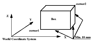
is used to define a world zone that has the shape of a straight box with all its sides parallel to the axes of the World Coordinate System.Example
System Data Types and Routines 2-WZBoxDef-465
VAR shapedata volume;
CONST pos corner1:=[200,100,100];
CONST pos corner2:=[600,400,400];
...
WZBoxDef \Inside, volume, corner1, corner2;
Define a straight box with coordinates parallel to the axes of the world coordinate system and defined by the opposite corners
corner1 and corner2.Arguments
WZBoxDef [\Inside] | [\Outside] Shape LowPoint HighPoint
\Inside
Data type: switchDefine the volume inside the box.
\Outside
Data type: switchDefine the volume outside the box (inverse volume).
One of the arguments
\Inside or \Outside must be specified.Shape
Data type: shapedataVariable for storage of the defined volume (private data for the system).
LowPoint
Data type: posPosition (x,y,x) in mm defining one lower corner of the box.
HighPoint
Data type: posPosition (x,y,z) in mm defining the corner diagonally opposite to the previous one.
Program execution
The definition of the box is stored in the variable of type
shapedata (argument Shape), for future use in WZLimSup or WZDOSet instructions.Limitations
The
LowPoint and HighPoint positions must be valid for opposite corners (with different x, y and z coordinate values).If the robot is used to point out the LowPoint or HighPoint, work object wobj0 must be active (use of component trans in robtarget e.g. p1.trans as argument).Syntax
WZBoxDef
[’\’Inside] | [’\’Outside] ’,’
[Shape’:=’]<variable (
VAR) of shapedata>’,’[LowPoint’:=’]<expression (
IN) of pos>’,’[HighPoint’:=’]<expression (
IN) of pos>’;’
WZCylDef Define a cylinder-shaped world zone
WZCylDef (World Zone Cylinder Definition)
is used to define a world zone that has the shape of a cylinder with the cylinder axis parallel to the z-axis of the World Coordinate System.Example
System Data Types and Routines 2-WZCylDef-467
VAR shapedata volume;
CONST pos C2:=[300,200,200];
CONST num R2:=100;
CONST num H2:=200;
...
WZCylDef \Inside, volume, C2, R2, H2;
Define a cylinder with the centre of the bottom circle in
C2, radius R2 and heightH2
.Arguments
WZCylDef [\Inside] | [\Outside] Shape CentrePoint Radius Height
\Inside
Data type: switchDefine the volume inside the cylinder.
\Outside
Data type: switchDefine the volume outside the cylinder (inverse volume).
One of the arguments
\Inside or \Outside must be specified.Shape
Data type: shapedataVariable for storage of the defined volume (private data for the system).
CentrePoint
Data type: posPosition (x,y,z) in mm defining the centre of one circular end of the cylinder.
Radius
Data type: numThe radius of the cylinder in mm.
Height
Data type: numThe height of the cylinder in mm.
If it is positive (+z direction), the
CentrePoint argument is the centre of the lower end of the cylinder (as in the above example). If it is negative (-z direction), the CentrePoint argument is the centre of the upper end of the cylinder.Program execution
The definition of the cylinder is stored in the variable of type
shapedata (argument Shape), for future use in WZLimSup or WZDOSet instructions.Limitations
If the robot is used to point out the
CentrePoint, work object wobj0 must be active (use of component trans in robtarget e.g. p1.trans as argument).Syntax
WZCylDef
[’\’Inside] | [’\’Outside]’,’
[Shape’:=’]<variable (
VAR) of shapedata>’,’[CentrePoint’:=’]<expression (
IN) of pos>’,’[Radius’:=’]<expression (
IN) of num>’,’[Height’:=’]<expression (
IN) of num>’;’
WZDisable Deactivate temporary world zone supervision
WZDisable (World Zone Disable)
is used to deactivate the supervision of a temporary world zone, previously defined either to stop the movement or to set an output.Example
VAR wztemporary wzone;
...
PROC ...
WZLimSup \Temp, wzone, volume;
MoveL p_pick, v500, z40, tool1;
WZDisable wzone;
MoveL p_place, v200, z30, tool1;
ENDPROC
When moving to
p_pick, the position of the robot’s TCP is checked so that it will not go inside the specified volume wzone. This supervision is not performed when going to p_place.Arguments
WZDisable WorldZone
WorldZone
Data type: wztemporaryVariable or persistent variable of type
wztemporary, which contains the identity of the world zone to be deactivated.Program execution
The temporary world zone is deactivated. This means that the supervision of the robot’s TCP, relative to the corresponding volume, is temporarily stopped. It can be reactivated via the
WZEnable instruction.Limitations
Only a temporary world zone can be deactivated. A stationary world zone is always active.
Syntax
WZDisable
[WorldZone’:=’]<variable or persistent (
INOUT) of wztemporary>’;’
WZDOSet Activate world zone to set digital output
WZDOSet (World Zone Digital Output Set)
is used to define the action and to activate a world zone for supervision of the robot movements. After this instruction is executed, when the robot’s TCP is inside the defined world zone or is approaching close to it, a digital output signal is set to the specified value.Example
VAR wztemporary service;
PROC zone_output()
VAR shapedata volume;
CONST pos p_service:=[500,500,700];
...
WZSphDef \Inside, volume, p_service, 50;
WZDOSet \Temp, service \Inside, volume, do_service, 1;
ENDPROC
Definition of temporary world zone
service in the application program, that sets the signal do_service, when the robot’s TCP is inside the defined sphere during program execution or when jogging.Arguments
WZDOSet [\Temp] | [\Stat] WorldZone [\Inside] | [\Before] Shape
Signal SetValue
\Temp
(Temporary) Data type: switchThe world zone to define is a temporary world zone.
\Stat
(Stationary) Data type: switchThe world zone to define is a stationary world zone.
One of the arguments
\Temp or \Stat must be specified.WorldZone
Data type: wztemporaryVariable or persistent variable, that will be updated with the identity (numeric value) of the world zone. If use of switch
\Temp, the data type must be wztemporary. If use of switch \Stat, the data type must be wzstationary.\Inside
Data type: switchThe digital output signal will be set when the robot’s TCP is inside the defined volume.
\Before
Data type: switchThe digital output signal will be set before the robot’s TCP reaches the defined volume (as soon as possible before the volume). One of the arguments
\Inside or \Outside must be specified.Shape
Data type: shapedataThe variable that defines the volume of the world zone.
Signal
Data type: signaldoThe name of the digital output signal that will be changed. If a stationary worldzone is used, the signal must be write protected for access from the user (RAPID, TP). Set Access = System for the signal in System Parameters.
SetValue
Data type: dionumDesired value of the signal (0 or 1) when the robot’s TCP is inside the volume or just before it enters the volume. When outside or just outside the volume, the signal is set to the opposite value.
Program execution
The defined world zone is activated. From this moment, the robot’s TCP position is supervised and the output will be set, when the robot’s TCP position is inside the volume (
\Inside) or comes close to the border of the volume (\Before).Example
VAR wztemporary home;
VAR wztemporary service;
PERS wztemporary equip1:=[0];
PROC main()
...
! Definition of all temporary world zones
zone_output;
...
! equip1 in robot work area
WZEnable equip1;
...
! equip1 out of robot work area
WZDisable equip1;
...
! No use for equip1 any more
WZFree equip1;
...
ENDPROC
PROC zone_output()
VAR shapedata volume;
CONST pos p_home:=[800,0,800];
CONST pos p_service:=[800,800,800];
CONST pos p_equip1:=[-800,-800,0];
...
WZSphDef \Inside, volume, p_home, 50;
WZDOSet \Temp, home \Inside, volume, do_home, 1;
WZSphDef \Inside, volume, p_service, 50;
WZDOSet \Temp, service \Inside, volume, do_service, 1;
WZCylDef \Inside, volume, p_equip1, 300, 1000;
WZLimSup \Temp, equip1, volume;
! equip1 not in robot work area
WZDisable equip1;
ENDPROC
Definition of temporary world zones
home and service in the application program, that sets the signals do_home and do_service, when the robot is inside the sphere home or service respectively during program execution or when jogging. Also, definition of a temporary world zone equip1, which is active only in the part of the robot program when equip1 is inside the working area for the robot. At that time the robot stops before entering the equip1 volume, both during program execution and manual jogging. equip1 can be disabled or enabled from other program tasks by using the persistent variable equip1 value.Limitations
A world zone cannot be redefined by using the same variable in the argument
WorldZone
.A stationary world zone cannot be deactivated, activated again or erased in the RAPID program. A temporary world zone can be deactivated (
WZDisable), activated again (WZEnable) or erased (WZFree) in the RAPID program.Syntax
WZDOSet
(’\’Temp) | (’\’Stat) ’,’
[WorldZone’:=’]<variable or persistent (
INOUT) of wztemporary>(’\’Inside) | (’\’Before) ’,’
[Shape’:=’]<variable (
VAR) of shapedata>’,’[Signal’:=’]<variable (
VAR) of signaldo>’,’[SetValue’:=’]<expression (
IN) of dionum>’;’
WZEnable Activate temporary world zone supervision
WZEnable (World Zone Enable)
is used to re-activate the supervision of a temporary world zone, previously defined either to stop the movement or to set an output.Example
VAR wztemporary wzone;
...
PROC ...
WZLimSup \Temp, wzone, volume;
MoveL p_pick, v500, z40, tool1;
WZDisable wzone;
MoveL p_place, v200, z30, tool1;
WZEnable wzone;
MoveL p_home, v200, z30, tool1;
ENDPROC
When moving to
p_pick, the position of the robot’s TCP is checked so that it will not go inside the specified volume wzone. This supervision is not performed when going to p_place, but is reactivated before going to p_homeArguments
WZEnable WorldZone
WorldZone
Data type: wztemporaryVariable or persistent variable of the type
wztemporary, which contains the identity of the world zone to be activated.Program execution
The temporary world zone is re-activated. Please note that a world zone is automatically activated when it is created. It need only be re-activated when it has previously been deactivated by
WZDisable.Limitations
Only a temporary world zone can be deactivated and reactivated. A stationary world zone is always active.
Syntax
WZEnable
[WorldZone’:=’]<variable or persistent (
INOUT) of wztemporary>’;’
WZFree Erase temporary world zone supervision
WZFree (World Zone Free)
is used to erase the definition of a temporary world zone, previously defined either to stop the movement or to set an output.Example
VAR wztemporary wzone;
...
PROC ...
WZLimSup \Temp, wzone, volume;
MoveL p_pick, v500, z40, tool1;
WZDisable wzone;
MoveL p_place, v200, z30, tool1;
WZEnable wzone;
MoveL p_home, v200, z30, tool1;
WZFree wzone;
ENDPROC
When moving to
p_pick, the position of the robot’s TCP is checked so that it will not go inside a specified volume wzone. This supervision is not performed when going to p_place, but is reactivated before going to p_home. When this position is reached, the world zone definition is erased.Arguments
WZFree WorldZone
WorldZone
Data type: wztemporaryVariable or persistent variable of the type
wztemporary, which contains the identity of the world zone to be erased.Program execution
The temporary world zone is first deactivated and then its definition is erased Once erased, a temporary world zone cannot be either re-activated nor deactivated.
Limitations
Only a temporary world zone can be deactivated, reactivated or erased. A stationary world zone is always active.
Syntax
WZFree
[WorldZone’:=’]<variable or persistent (
INOUT) of wztemporary>’;’
WZLimSup Activate world zone limit supervision
WZLimSup (World Zone Limit Supervision)
is used to define the action and to activate a world zone for supervision of the working area of the robot. After this instruction is executed, when the robot’s TCP reaches the defined world zone, the movement is stopped both during program execution and when jogging.Example
VAR wzstationary max_workarea;
...
PROC POWER_ON()
VAR shapedata volume;
...
WZBoxDef \Outside, volume, corner1, corner2;
WZLimSup \Stat, max_workarea, volume;
ENDPROC
Definition and activation of stationary world zone
max_workarea, with the shape of the area outside a box (temporarily stored in volume) and the action work-area supervision. The robot stops with an error message before entering the area outside the box.Arguments
WZLimSup [\Temp] | [\Stat] WorldZone Shape
\Temp
(Temporary) Data type: switchThe world zone to define is a temporary world zone.
\Stat
(Stationary) Data type: switchThe world zone to define is a stationary world zone.
One of the arguments
\Temp or \Stat must be specified.WorldZone
Data type: wztemporaryVariable or persistent variable that will be updated with the identity (numeric value) of the world zone.If use of switch
\Temp, the data type must be wztemporary. If use of switch \Stat, the data type must be wzstationary.Shape
Data type: shapedataThe variable that defines the volume of the world zone.
Program execution
The defined world zone is activated. From this moment the robot’s TCP position is supervised. If it reaches the defined area the movement is stopped.
Example
VAR wzstationary box1_invers;
VAR wzstationary box2;
PROC wzone_power_on()
VAR shapedata volume;
CONST pos box1_c1:=[500,-500,0];
CONST pos box1_c2:=[-500,500,500];
CONST pos box2_c1:=[500,-500,0];
CONST pos box2_c2:=[200,-200,300];
...
WZBoxDef \Outside, volume, box1_c1, box1_c2;
WZLimSup \Stat, box1_invers, volume;
WZBoxDef \Inside, volume, box2_c1, box2_c2;
WZLimSup \Stat, box2, volume;
ENDPROC
Limitation of work area for the robot with the following stationary world zones:
- Outside working area when outside box1_invers
- Outside working area when inside box2
If this routine is connected to the system event POWER ON, these world zones will always be active in the system, both for program movements and manual jogging.
Limitations
A world zone cannot be redefined using the same variable in argument
WorldZone. A stationary world zone cannot be deactivated, activated again or erased in the RAPID program. A temporary world zone can be deactivated (WZDisable), activated again (WZEnable) or erased (WZFree) in the RAPID program.Syntax
WZLimSup
[’\’Temp] | [’\Stat]’,’
[WorldZone’:=’]<variable or persistent (
INOUT) of wztemporary>’,’[Shape’:=’] <variable (
VAR) of shapedata>’;’
WZSphDef Define a sphere-shaped world zone
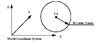
WZSphDef (World Zone Sphere Definition)
is used to define a world zone that has the shape of a sphere.Example
System Data Types and Routines 2-WZSphDef-485
VAR shapedata volume;
CONST pos C1:=[300,300,200];
CONST num R1:=200;
...
WZSphDef \Inside, volume, C1, R1;
Define a sphere named
volume by its centre C1 and its radius R1.Arguments
WZSphDef [\Inside] | [\Outside] Shape CentrePoint Radius
\Inside
Data type: switchDefine the volume inside the sphere.
\Outside
Data type: switchDefine the volume outside the sphere (inverse volume).
One of the arguments
\Inside or \Outside must be specified.Shape
Data type: shapedataVariable for storage of the defined volume (private data for the system).
CentrePoint
Data type: posPosition (x,y,z) in mm defining the centre of the sphere.
Radius
Data type: numThe radius of the sphere in mm.
Program execution
The definition of the sphere is stored in the variable of type
shapedata (argument Shape), for future use in WZLimSup or WZDOSet instructions.Limitations
If the robot is used to point out the
CentrePoint, work object wobj0 must be active (use of component trans in robtarget e.g. p1.trans as argument).Syntax
WZSphDef
[’\’Inside] | [’\’Outside]’,’
[Shape’:=’]<variable (
VAR) of shapedata>’,’[CentrePoint’:=’]<expression (
IN) of pos>’,’[Radius’:=’]<expression (
IN) of num>’;’