":=" Assigns a value
The ":=" instruction is used to assign a new value to data. This value can be anything from a constant value to an arithmetic expression, e.g. reg1+5*reg3.
Examples
reg1 := 5;
reg1 is assigned the value 5.
reg1 := reg2 - reg3;
reg1 is assigned the value that the reg2-reg3 calculation returns.
counter := counter + 1;
counter is incremented by one.
Arguments
Data := Value
Data Data type: All
The data that is to be assigned a new value.
Value Data type: Same as Data
The desired value.
Examples
tool1.tframe.trans.x := tool1.tframe.trans.x + 20;
The TCP for tool1 is shifted 20 mm in the X-direction.
pallet{5,8} := Abs(value);
An element in the pallet matrix is assigned a value equal to the absolute value of the value variable.
Limitations
The data (whose value is to be changed) must not be
- a constant
- a non-value data type.
The data and value must have similar (the same or alias) data types.
Syntax
(EBNF)
<assignment target> ’:=’ <expression> ’;’
<assignment target> ::=
<variable>
| <persistent>
| <parameter>
| <VAR>
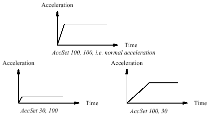
AccSet Reduces the acceleration
AccSet is used when handling fragile loads. It allows slower acceleration and deceler-ation, which results in smoother robot movements.
Examples
AccSet 50, 100;
The acceleration is limited to 50% of the normal value.
AccSet 100, 50;
The acceleration ramp is limited to 50% of the normal value.
Arguments
AccSet Acc Ramp
Acc Data type: num
Acceleration and deceleration as a percentage of the normal values.
100% corresponds to maximum acceleration. Maximum value: 100%.
Input value < 20% gives 20% of maximum acceleration.
Ramp Data type: num
The rate at which acceleration and deceleration increases as a percentage of the normal values (see Figure 17). Jerking can be restricted by reducing this value.
100% corresponds to maximum rate. Maximum value: 100%.
Input value < 10% gives 10% of maximum rate.
Reducing the acceleration results in smoother movements.
Program execution
The acceleration applies to both the robot and external axes until a new AccSet instruc-tion is executed.
The default values (100%) are automatically set
- at a cold start-up
- when a new program is loaded
- when starting program executing from the beginning.
Syntax
AccSet
[ Acc ’:=’ ] < expression (IN) of num > ’,’
[ Ramp ’:=’ ] < expression (IN) of num > ’;’
ActUnit Activates a mechanical unit
ActUnit is used to activate a mechanical unit.
It can be used to determine which unit is to be active when, for example, common drive units are used.
Example
ActUnit orbit_a;
Activation of the orbit_a mechanical unit.
Arguments
ActUnit MecUnit
MecUnit (Mechanical Unit) Data type: mecunit
The name of the mechanical unit that is to be activated.
Program execution
When the robot and external axes have come to a standstill, the specified mechanical unit is activated. This means that it is controlled and monitored by the robot. If several mechanical units share a common drive unit, activation of one of these mechanical units will also connect that unit to the common drive unit.
Limitations
Instruction ActUnit cannot be used in
- program sequence StorePath ... RestoPath
- event routine RESTART
The movement instruction previous to this instruction, should be terminated with a stop point in order to make a restart in this instruction possible following a power fail-ure.
Syntax
ActUnit
[MecUnit ’:=’ ] < variable (VAR) of mecunit> ’;’
Add Adds a numeric value
Add is used to add or subtract a value to or from a numeric variable or persistent.
Examples
Add reg1, 3;
3 is added to reg1, i.e. reg1:=reg1+3.
Add reg1, -reg2;
The value of reg2 is subtracted from reg1, i.e. reg1:=reg1-reg2.
Arguments
Add Name AddValue
Name Data type: num
The name of the variable or persistent to be changed.
AddValue Data type: num
The value to be added.
Syntax
Add
[ Name ’:=’ ] < var or pers (INOUT) of num > ’,’
[ AddValue ’:=’ ] < expression (IN) of num > ’;’
AliasIO Define I/O signal with alias name
AliasIO is used to define a signal of any type with an alias name or to use signals in built-in task modules.Signals with alias names can be used for predefined generic programs, without any modification of the program before running in different robot installations. The instruction AliasIO must be run before any use of the actual signal.
Example 1
VAR signaldo alias_do;
PROC prog_start()
AliasIO config_do, alias_do;
ENDPROC
The routine prog_start is connected to the START event in system parameters.The program defined digital output signal alias_do is connected to the config-ured digital output signal config_do at program start (start the program from beginning).
Arguments
AliasIO FromSignal ToSignal
FromSignal Data type: signalxx or string
Loaded modules:
The signal identifier named according to the configuration (data type signalxx) from which the signal descriptor is copied. The signal must be defined in the IO configuration.
Built-in modules:
A reference (CONST, VAR, PERS or parameter of these) containing the name of the signal (data type string) from which the signal descriptor after search in the system is copied. The signal must be defined in the IO configuration.
ToSignal Data type: signalxx
The signal identifier according to the program (data type signalxx) to which the signal descriptor is copied. The signal must be declared in the RAPID program. The same data type must be used (or find) for the arguments FromSignal and ToSignal and must be one of type signalxx (signalai, signalao, signaldi, signaldo, signalgi or sig-nalgo).
Program execution
The signal descriptor value is copied from the signal given in argument FromSignal to the signal given in argument ToSignal.
Example 2
VAR signaldi alias_di;
PROC prog_start()
CONST string config_string := "config_di";
AliasIO config_string, alias_di;
ENDPROC
The routine prog_start is connected to the START event in system parameters.The program defined digital output signal alias_di is connected to the configured digital output signal config_di (via constant config_string) at program start (start the program from the beginning).
Limitation
When starting the program, the alias signal cannot be used until the AliasIO instruction is executed.
Instruction AliasIO must be placed
- either in the event routine executed at program start (event START)
- or in the program part executed after every program start (before use of the signal)
Instruction AliasIO is not available for programming from the Teach Pendant (only from Program Maker). Option Developer’s Functions is required.
Syntax
AliasIO
[ FromSignal ’:=’ ] < reference (REF) of anytype> ’,’
[ ToSignal ’:=’ ] < variable (VAR) of anytype> ’;’
Break Break program execution
Break is used to make an immediate break in program execution for RAPID program code debugging purposes.
Example
..Break;
..Program execution stops and it is possible to analyse variables, values etc. for debugging purposes.
Program execution
The instruction stops program execution at once, without waiting for the robot and external axes to reach their programmed destination points for the movement being performed at the time. Program execution can then be restarted from the next instruction. If there is a Break instruction in some event routine, the routine will be executed from the beginning of the next event.
Syntax
Break’;’
ProcCall Calls a new procedure
A procedure call is used to transfer program execution to another procedure. When the procedure has been fully executed, program execution continues with the instruction following the procedure call. It is usually possible to send a number of arguments to the new procedure. These control the behaviour of the procedure and make it possible for the same procedure to be used for different things.
Examples
weldpipe1;
Calls the weldpipe1 procedure.errormessage;
Set do1;
.PROC errormessage()
TPWrite "ERROR";
ENDPROC
The errormessage procedure is called. When this procedure is ready, program execution returns to the instruction following the procedure call, Set do1.
Arguments
Procedure { Argument }
Procedure Identifier
The name of the procedure to be called.
Argument Data type: In accordance with the procedure declaration
The procedure arguments (in accordance with the parameters of the procedure).
Example
weldpipe2 10, lowspeed;
Calls the weldpipe2 procedure, including two arguments.weldpipe3 10 \speed:=20;
Calls the weldpipe3 procedure, including one mandatory and one optional argument.
Limitations
The procedure’s arguments must agree with its parameters:
- All mandatory arguments must be included.
- They must be placed in the same order.
- They must be of the same data type.
- They must be of the correct type with respect to the access-mode (input, variable or persistent).
A routine can call a routine which, in turn, calls another routine, etc. A routine can also call itself, i.e. a recursive call. The number of routine levels permitted depends on the number of parameters, but more than 10 levels are usually permitted.
Syntax
(EBNF)
<procedure> [ <argument list> ] ’;’
<procedure> ::= <identifier>
CallByVar Call a procedure by a variable
CallByVar (Call By Variable) can be used to call procedures with specific names, e.g. proc_name1, proc_name2, proc_name3 ... proc_namex via a variable.
Example
reg1 := 2;
CallByVar "proc", reg1;
The procedure proc2 is called.
Arguments
CallByVar Name Number
Name Data type: string
The first part of the procedure name, e.g. proc_name.
Number Data type: num
The numeric value for the number of the procedure. This value will be converted to a string and gives the 2:nd part of the procedure name e.g. 1. The value must be a positive integer.
Example
Static selection of procedure call
TEST reg1
CASE 1:
lf_door door_loc;
CASE 2:
rf_door door_loc;
CASE 3:
lr_door door_loc;
CASE 4:
rr_door door_loc;
DEFAULT:
EXIT;
ENDTEST
Depending on whether the value of register reg1 is 1, 2, 3 or 4, different procedures are called that perform the appropriate type of work for the selected door.
The door location in argument door_loc.
Dynamic selection of procedure call with RAPID syntax
reg1 := 2;
%"proc"+NumToStr(reg1,0)% door_loc;
The procedure proc2 is called with argument door_loc.
Limitation: All procedures must have a specific name e.g. proc1, proc2, proc3.
Dynamic selection of procedure call with CallByVar
reg1 := 2;
CallByVar "proc",reg1;
The procedure proc2 is called.
Limitation: All procedures must have specific name, e.g. proc1, proc2, proc3,and no arguments can be used.
Limitations
Can only be used to call procedures without parameters. Execution of CallByVar takes a little more time than execution of a normal procedure call.
Error handling
In the event of a reference to an unknown procedure, the system variable ERRNO is set to ERR_REFUNKPRC. In the event of the procedure call error (not procedure), the system variable ERRNO is set to ERR_CALLPROC. These errors can be handled in the error handler.
Syntax
CallByVar
[Name ‘:=’] <expression (IN) of string>’,’
[Number ‘:=‘] <expression (IN) of num>’;’
Clear Clears the value
Clear is used to clear a numeric variable or persistent , i.e. it sets it to 0.
Example
Clear reg1;
Reg1 is cleared, i.e. reg1:=0.
Arguments
Clear Name
Name Data type: num
The name of the variable or persistent to be cleared.
Syntax
Clear
[ Name ’:=’ ] < var or pers (INOUT) of num > ’;’
ClkReset Resets a clock used for timing
ClkReset is used to reset a clock that functions as a stop-watch used for timing. This instruction can be used before using a clock to make sure that it is set to 0.
Example
ClkReset clock1;The clock clock1 is reset.
Arguments
ClkReset Clock
Clock Data type: clock The name of the clock to reset.
Program execution
When a clock is reset, it is set to 0.If a clock is running, it will be stopped and then reset.
Syntax
ClkReset
[ Clock ’:=’ ] < variable (VAR) of clock > ’;’
ClkStart Starts a clock used for timing
ClkStart is used to start a clock that functions as a stop-watch used for timing.
Example
ClkStart clock1;
The clock clock1 is started.
Arguments
ClkStart Clock
Clock Data type: clock
The name of the clock to start.
Program execution
When a clock is started, it will run and continue counting seconds until it is stopped.A clock continues to run when the program that started it is stopped. However, the event that you intended to time may no longer be valid. For example, if the program was measuring the waiting time for an input, the input may have been received while the program was stopped. In this case, the program will not be able to "see" the event that occurred while the program was stopped. A clock continues to run when the robot is powered down as long as the battery back-up retains the program that contains the clock variable. If a clock is running it can be read, stopped or reset.
Example
VAR clock clock2;
ClkReset clock2;
ClkStart clock2;
WaitUntil DInput(di1) = 1;
ClkStop clock2;
time:=ClkRead(clock2);
The waiting time for di1 to become 1 is measured.
Syntax
ClkStart
[ Clock ’:=’ ] < variable (VAR) of clock > ’;’
ClkStop Stops a clock used for timing
ClkStop is used to stop a clock that functions as a stop-watch used for timing.
Example
ClkStop clock1;
The clock clock1 is stopped.
Arguments
ClkStop Clock
Clock Data type: clock
The name of the clock to stop.
Program execution
When a clock is stopped, it will stop running.If a clock is stopped, it can be read, started again or reset.
Syntax
ClkStop
[ Clock ’:=’ ] < variable (VAR) of clock > ’;’
Close Closes a file or serial channel
Close is used to close a file or serial channel.
Example
Close channel2;The serial channel referred to by channel2 is closed.
Arguments
Close IODevice
IODevice Data type: iodev
The name (reference) of the file or serial channel to be closed.
Program execution
The specified file or serial channel is closed and must be re-opened before reading or writing. If it is already closed, the instruction is ignored.
Syntax
Close
[IODevice ’:=’] <variable (VAR) of iodev>’;’
ClearIOBuff Clear input buffer of a serial channel
ClearIOBuff (Clear I/O Buffer) is used to clear the input buffer of a serial channel. All buffered characters from the input serial channel are discarded.
Example
VAR iodev channel2;
.Open "sio1:", channel2 \Bin;
ClearIOBuff channel2;
The input buffer for the serial channel referred to by channel2 is cleared.
Arguments
ClearIOBuff IODevice
IODevice Data type: iodev
The name (reference) of the serial channel whose input buffer is to be cleared.
Program execution
All buffered characters from the input serial channel are discarded. Next read instruc-tions will wait for new input from the channel.
Limitations
This instruction can only be used for serial channels.
Syntax
ClearIOBuff
[IODevice ’:=’] <variable (VAR) of iodev>’;’
comment Comment
Comment is only used to make the program easier to understand. It has no effect on the execution of the program.
Example
! Goto the position above pallet
MoveL p100, v500, z20, tool1;
A comment is inserted into the program to make it easier to understand.
Arguments
! Comment
Comment Text string
Any text.
Program execution
Nothing happens when you execute this instruction.
Syntax
(EBNF)
’!’ {<character>} <newline>
ConfJ Controls the configuration during joint movement
ConfJ (Configuration Joint) is used to specify whether or not the robot’s configuration is to be controlled during joint movement. If it is not controlled, the robot can some-times use a different configuration than that which was programmed. With ConfJ\Off, the robot cannot switch main axes configuration - it will search for a solution with the same main axes configuration as the current one. It moves to the clos-est wrist configuration for axes 4 and 6.
Examples
ConfJ \Off;
MoveJ *, v1000, fine, tool1;
The robot moves to the programmed position and orientation. If this position can be reached in several different ways, with different axis configurations, the clos-est possible position is chosen.
ConfJ \On;
MoveJ *, v1000, fine, tool1;
The robot moves to the programmed position, orientation and axis configuration. If this is not possible, program execution stops.
Arguments
ConfJ [\On] | [\Off]
\On Data type: switch
The robot always moves to the programmed axis configuration. If this is not pos-sible using the programmed position and orientation, program execution stops. The IRB5400 robot will move to the pogrammed axis configuration or to an axis configuration close the the programmed one. Program execution will not stop if it is impossible to reach the programmed axis configuration.
\Off Data type: switch
The robot always moves to the closest axis configuration.
Program execution
If the argument \On (or no argument) is chosen, the robot always moves to the pro-grammed axis configuration. If this is not possible using the programmed position and orientation, program execution stops before the movement starts. If the argument \Off is chosen, the robot always moves to the closest axis configuration. This may be different to the programmed one if the configuration has been incorrectly specified manually, or if a program displacement has been carried out.The control is active by default. This is automatically set
- at a cold start-up
- when a new program is loaded
- when starting program executing from the beginning.
Syntax
ConfJ
[ ’\’ On] | [ ’\’ Off] ’;’
ConfL Monitors the configuration during linear movement
ConfL (Configuration Linear) is used to specify whether or not the robot’s configura-tion is to be monitored during linear or circular movement. If it is not monitored, the configuration at execution time may differ from that at programmed time. It may also result in unexpected sweeping robot movements when the mode is changed to joint movement.
NOTE: For the IRB 6400 robot the monotoring is always off independant of the switch.
Examples
ConfL \On;
MoveL *, v1000, fine, tool1;
Program execution stops when the programmed configuration is not possible to reach from the current position.
SingArea \Wrist;
Confl \On;
MoveL *, v1000, fine, tool1;
The robot moves to the programmed position, orientation and wrist axis config-uration. If this is not possible, program execution stops.
ConfL \Off;
MoveL *, v1000, fine, tool1;
No error message is displayed when the programmed configuration is not the same as the configuration achieved by program execution.
Arguments
ConfL [\On] | [\Off]
\On Data type: switch
The robot configuration is monitored.
\Off Data type: switch
The robot configuration is not monitored.
Program execution
During linear or circular movement, the robot always moves to the programmed posi-tion and orientation that has the closest possible axis configuration. If the argument \On (or no argument) is chosen, then the program execution stops as soon as: - the configuration of the programmed position will not be attained from the current position.
- the needed reorientation of any one of the wrist axes to get to the programmed position from the current position exceeds a limit (140-180 degrees). However, it is possible to restart the program again, although the wrist axes may con-tinue to the wrong configuration. At a stop point, the robot will check that the config-urations of all axes are achieved, not only the wrist axes. If SingArea\Wrist is also used, the robot always moves to the programmed wrist axes configuration and at a stop point the remaining axes configurations will be checked. If the argument \Off is chosen, there is no monitoring.Monitoring is active by default. This is automatically set
- at a cold start-up
- when a new program is loaded
- when starting program executing from the beginning.
Syntax
ConfL
[ ’\’ On] | [ ’\’ Off] ’;’
CONNECT Connects an interrupt to a trap routine
CONNECT is used to find the identity of an interrupt and connect it to a trap routine.The interrupt is defined by ordering an interrupt event and specifying its identity. Thus, when that event occurs, the trap routine is automatically executed.
Example
VAR intnum feeder_low;
CONNECT feeder_low WITH feeder_empty;
ISignalDI di1, 1 , feeder_low;
An interrupt identity feeder_low is created which is connected to the trap routine feeder_empty. The interrupt is defined as input di1 is getting high. In other words, when this signal becomes high, the feeder_empty trap routine is executed.
Arguments
CONNECT Interrupt WITH Trap routine
Interrupt Data type: intnum
The variable that is to be assigned the identity of the interrupt.
This must not be declared within a routine (routine data).
Trap routine Identifier
The name of the trap routine.
Program execution
The variable is assigned an interrupt identity which can then be used when ordering or disabling interrupts. This identity is also connected to the specified trap routine. Note that before an event can be handled, an interrupt must also be ordered, i.e. the event specified.
Limitations
An interrupt (interrupt identity) cannot be connected to more than one trap routine.Different interrupts, however, can be connected to the same trap routine. When an interrupt has been connected to a trap routine, it cannot be reconnected or transferred to another routine; it must first be deleted using the instruction IDelete.
Error handling
If the interrupt variable is already connected to a TRAP routine, the system variable ERRNO is set to ERR_ALRDYCNT.
If the interrupt variable is not a variable reference, the system variable ERRNO is set to ERR_CNTNOTVAR.
If no more interrupt numbers are available, the system variable ERRNO is set to ERR_INOMAX.
These errors can be handled in the ERROR handler.
Syntax
(EBNF)
CONNECT <connect target> WITH <trap>‘;’
<connect target> ::= <variable>
| <parameter>
| <VAR>
<trap> ::= <identifier>
DeactUnit Deactivates a mechanical unit
DeactUnit is used to deactivate a mechanical unit.It can be used to determine which unit is to be active when, for example, common drive units are used.
Examples
DeactUnit orbit_a;
Deactivation of the orbit_a mechanical unit.
MoveL p10, v100, fine, tool1;
DeactUnit track_motion;
MoveL p20, v100, z10, tool1;
MoveL p30, v100, fine, tool1;
ActUnit track_motion;
MoveL p40, v100, z10, tool1;
The unit track_motion will be stationary when the robot moves to p20 and p30.
After this, both the robot and track_motion will move to p40.
MoveL p10, v100, fine, tool1;
DeactUnit orbit1;
ActUnit orbit2;
MoveL p20, v100, z10, tool1;
The unit orbit1 is deactivated and orbit2 activated.
Arguments
DeactUnit MecUnit
MecUnit (Mechanical Unit) Data type: mecunit
The name of the mechanical unit that is to be deactivated.
Program execution
When the robot and external axes have come to a standstill, the specified mechanical unit is deactivated. This means that it will neither be controlled nor monitored until it is re-activated. If several mechanical units share a common drive unit, deactivation of one of the mechanical units will also disconnect that unit from the common drive unit.
Limitations
Instruction DeactUnit cannot be used
- in program sequence StorePath ... RestoPath
- in event routine RESTART
- when one of the axes in the mechanical unit is in independent mode.
The movement instruction previous to this instruction, should be terminated with a stop point in order to make a restart in this instruction possible following a power failure.
Syntax
DeactUnit
[MecUnit ’:=’ ] < variable (VAR) of mecunit> ’;’
Decr Decrements by 1
Decr is used to subtract 1 from a numeric variable or persistent.
Example
Decr reg1;
1 is subtracted from reg1, i.e. reg1:=reg1-1.
Arguments
Decr Name
Name Data type: num
The name of the variable or persistent to be decremented.
Example
TPReadNum no_of_parts, "How many parts should be produced? ";
WHILE no_of_parts>0 DO
produce_part;
Decr no_of_parts;
ENDWHILE
The operator is asked to input the number of parts to be produced. The variable no_of_parts is used to count the number that still have to be produced.
Syntax
Decr
[ Name ’:=’ ] < var or pers (INOUT) of num > ’;’
EOffsOff Deactivates an offset for external axes
EOffsOff (External Offset Off) is used to deactivate an offset for external axes. The offset for external axes is activated by the instruction EOffsSet or EOffsOn and applies to all movements until some other offset for external axes is activated or until the offset for external axes is deactivated.
Examples
EOffsOff;
Deactivation of the offset for external axes.
MoveL p10, v500, z10, tool1;
EOffsOn \ExeP:=p10, p11;
MoveL p20, v500, z10, tool1;
MoveL p30, v500, z10, tool1;
EOffsOff;
MoveL p40, v500, z10, tool1;
An offset is defined as the difference between the position of each axis at p10 and
p11. This displacement affects the movement to p20 and p30, but not to p40.
Program execution
Active offsets for external axes are reset.
Syntax
EOffsOff ‘;’
EOffsOn Activates an offset for external axes
EOffsOn (External Offset On) is used to define and activate an offset for external axes using two positions.
Examples
MoveL p10, v500, z10, tool1;
EOffsOn \ExeP:=p10, p20;
Activation of an offset for external axes. This is calculated for each axis based on the difference between positions p10 and p20.
MoveL p10, v500, fine, tool1;
EOffsOn *;
Activation of an offset for external axes. Since a stop point has been used in the previous instruction, the argument \ExeP does not have to be used. The displace-ment is calculated on the basis of the difference between the actual position of each axis and the programmed point (*) stored in the instruction.
Arguments
EOffsOn [ \ExeP ] ProgPoint
[\ExeP ] (Executed Point) Data type: robtarget
The new position of the axes at the time of the program execution. If this argument is omitted, the current position of the axes at the time of the program execution is used.
ProgPoint (Programmed Point) Data type: robtarget
The original position of the axes at the time of programming.
Program execution
The offset is calculated as the difference between ExeP and ProgPoint for each separate external axis. If ExeP has not been specified, the current position of the axes at the time of the program execution is used instead. Since it is the actual position of the axes that is used, the axes should not move when EOffsOn is executed. This offset is then used to displace the position of external axes in subsequent position-ing instructions and remains active until some other offset is activated (the instruction EOffsSet or EOffsOn) or until the offset for external axes is deactivated (the instruction EOffsOff). Only one offset for each individual external axis can be activated at any one time. Sev-eral EOffsOn, on the other hand, can be programmed one after the other and, if they are, the different offsets will be added.
The external axes’ offset is automatically reset
- at a cold start-up
- when a new program is loaded
- when starting program executing from the beginning.
Example
SearchL sen1, psearch, p10, v100, tool1;
PDispOn \ExeP:=psearch, *, tool1;
EOffsOn \ExeP:=psearch, *;
A search is carried out in which the searched position of both the robot and the external axes is stored in the position psearch. Any movement carried out after this starts from this position using a program displacement of both the robot and the external axes. This is calculated based on the difference between the searched position and the programmed point (*) stored in the instruction.
Syntax
EOffsOn
[ ‘\’ ExeP ’:=’ < expression (IN) of robtarget > ’,’]
[ ProgPoint ’:=’ ] < expression (IN) of robtarget > ’;’
EOffsSet Activates an offset for external axes using a value
EOffsSet (External Offset Set) is used to define and activate an offset for external axes using values.
Example
VAR extjoint eax_a_p100 := [100, 0, 0, 0, 0, 0];
.EOffsSet eax_a_p100;
Activation of an offset eax_a_p100 for external axes, meaning (provided that the external axis "a" is linear) that:
- The ExtOffs coordinate system is displaced 100 mm for the logical axis "a"
- As long as this offset is active, all positions will be displaced 100 mm in the direction of the x-axis.
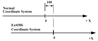
Displacement of an external axis.
Arguments
EOffsSet EAxOffs
EAxOffs (External Axes Offset) Data type: extjoint
The offset for external axes is defined as data of the type extjoint, expressed in:
- mm for linear axes
- degrees for rotating axes
Program execution
The offset for external axes is activated when the EOffsSet instruction is activated and remains active until some other offset is activated (the instruction EOffsSet or EOffsOn) or until the offset for external axes is deactivated (the EOffsOff). Only one offset for external axes can be activated at any one time. Offsets cannot be added to one another using EOffsSet. The external axes’ offset is automatically reset
- at a cold start-up
- when a new program is loaded
- when starting program executing from the beginning.
Syntax
EOffsSet
[ EAxOffs ’:=’ ] < expression (IN) of extjoint> ’;’
ErrWrite Write an Error Message
ErrWrite (Error Write) is used to display an error message on the teach pendant and write it in the robot message log.
Example
ErrWrite "PLC error", "Fatal error in PLC" \RL2:="Call service";
Stop;
A message is stored in the robot log. The message is also shown on the teach pendant display.
ErrWrite \ W, " Search error", "No hit for the first search";
RAISE try_search_again;
A message is stored in the robot log only. Program execution then continues.
Arguments
ErrWrite [ \W ] Header Reason [ \RL2] [ \RL3] [ \RL4]
[ \W ] (Warning) Data type: switch
Gives a warning that is stored in the robot error message log only (not shown directly on the teach pendant display).
Header Data type: string
Error message heading (max. 24 characters).
Reason Data type: string
Reason for error (line 1 of max. 40 characters).
[ \RL2] (Reason Line 2) Data type: string
Reason for error (line 2 of max. 40 characters).
[ \RL3] (Reason Line 3) Data type: string
Reason for error (line 3 of max. 40 characters).
[ \RL4] (Reason Line 4) Data type: string
Reason for error (line 4 of max. 40 characters).
Program execution
An error message (max. 5 lines) is displayed on the teach pendant and written in the robot message log. ErrWrite always generates the program error no. 80001 or in the event of a warning (argument \W) generates no. 80002.
Limitations
Total string length (Header+Reason+\RL2+\RL3+\RL4) is limited to 145 characters.
Syntax
ErrWrite
[ ’\’ W ’,’ ]
[ Header ’:=’ ] < expression (IN) of string> ‘,’
[ Reason ’:=’ ] < expression (IN) of string>
[ ’\’ RL2 ’:=’ < expression (IN) of string> ]
[ ’\’ RL3 ’:=’ < expression (IN) of string> ]
[ ’\’ RL4 ’:=’ < expression (IN) of string> ] ‘;’
EXIT Terminates program execution
EXIT is used to terminate program execution. Program restart will then be blocked, i.e. the program can only be restarted from the first instruction of the main routine (if the start point is not moved manually). The EXIT instruction should be used when fatal errors occur or when program execution is to be stopped permanently. The Stop instruction is used to temporarily stop program execution.
Example
ErrWrite "Fatal error","Illegal state";
EXIT;
Program execution stops and cannot be restarted from that position in the program.
Syntax
EXIT ’;’
ExitCycle Break current cycle and start next
ExitCycle is used to break the current cycle and move the PP back to the first instruction in the main routine. If the program is executed in continuous mode, it will start to execute the next cycle. If the execution is in cycle mode, the execution will stop at the first instruction in the main routine.
Example
VAR num cyclecount:=0;
VAR intnum error_intno;
PROC main()
IF cyclecount = 0 THEN
CONNECT error_intno WITH error_trap;
ISignalDI di_error,1,error_intno;
ENDIF
cyclecount:=cyclecount+1;
! start to do something intelligent
ENDPROC
TRAP error_trap
TPWrite "ERROR, I will start on the next item";
ExitCycle;
ENDTRAP
This will start the next cycle if the signal di_error is set.
Program execution
Execution of ExitCycle in the MAIN program task, results in the following in the
MAIN task:
- On-going robot movements stops
- All robot paths that are not performed at all path levels (both normal and
StorePath level) are cleared
- All instructions that are started but not finished at all execution levels (both normal and TRAP level) are interrupted
- The program pointer is moved to the first instruction in the main routine
- The program execution continues to execute the next cycle
Execution of ExitCycle in some other program task (besides MAIN) results in the following in the actual task:
- All instructions that are started but not finished on all execution levels (both normal and TRAP level) are interrupted
- The program pointer is moved to the first instruction in the main routine
- The program execution continues to execute the next cycle
All other modal things in the program and system are not affected by ExitCycle such as:
- The actual value of variables or persistents
- Any motion settings such as StorePath-RestoPath sequence, world zones, etc.
- Open files, directories, etc.
- Defined interrupts, etc.
Syntax
ExitCycle’;’
FOR Repeats a given number of times
FOR is used when one or several instructions are to be repeated a number of times. If the instructions are to be repeated as long as a given condition is met, the WHILE instruction is used.
Example
FOR i FROM 1 TO 10 DO
routine1;
ENDFOR
Repeats the routine1 procedure 10 times.
Arguments
FOR Loop counter FROM Start value TO End value
[STEP Step value] DO ... ENDFOR
Loop counter Identifier
The name of the data that will contain the value of the current loop counter.
The data is declared automatically and its name should therefore not be the same as the name of any data that exists already.
Start value Data type: Num
The desired start value of the loop counter. (usually integer values)
End value Data type: Num
The desired end value of the loop counter. (usually integer values)
Step value Data type: Num
The value by which the loop counter is to be incremented (or decremented) each loop. (usually integer values) If this value is not specified, the step value will automatically be set to 1 (or -1 if the start value is greater than the end value).
Example
FOR i FROM 10 TO 2 STEP -1 DO
a{i} := a{i-1};
ENDFOR
The values in an array are adjusted upwards so that a{10}:=a{9}, a{9}:=a{8} etc.
Program execution
1. The expressions for the start, end and step values are calculated.
2. The loop counter is assigned the start value.
3. The value of the loop counter is checked to see whether its value lies between the start and end value, or whether it is equal to the start or end value. If the value of the loop counter is outside of this range, the FOR loop stops and program execution con-tinues with the instruction following ENDFOR.
4. The instructions in the FOR loop are executed.
5. The loop counter is incremented (or decremented) in accordance with the step value.
6. The FOR loop is repeated, starting from point 3.
Limitations
The loop counter (of data type num) can only be accessed from within the FOR loop and consequently hides other data and routines that have the same name. It can only be read (not updated) by the instructions in the FOR loop. Decimal values for start, end or stop values, in combination with exact termination con-ditions for the FOR loop, cannot be used (undefined whether or not the last loop is run-ning).
Syntax
(EBNF)
FOR <loop variable> FROM <expression> TO <expression>
[ STEP <expression> ] DO
<instruction list>
ENDFOR
<loop variable> ::= <identifier>
GetSysData Get system data
GetSysData fetches the value and optional symbol name for the current system data of specified data type.With this instruction it is possible to fetch data for and the name of the current active Tool or Work Object.
Example
PERS tooldata curtoolvalue := [TRUE, [[0, 0, 0], [1, 0, 0, 0]],
[0, [0, 0, 0], [1, 0, 0, 0], 0, 0, 0]];
VAR string curtoolname;
GetSysData curtoolvalue;
Copy current active tool data value to the persistent variable curtoolvalue.
GetSysData curtoolvalue \ObjectName := curtoolname;
Copy also current active tool name to the variable curtoolname.
Arguments
GetSysData DestObject [\ ObjectName ]
DestObject Data type: anytype
Persistent for storage of current active system data value.
The data type of this argument also specifies the type of system data (Tool or Work Object) to fetch.
[\ObjectName] Data type: string
Option argument (variable or persistent) to also fetch the current active system data name.
Program execution
When running the instruction GetSysData the current data value is stored in the speci-fied persistent in argument DestObject. If argument \ObjectName is used, the name of the current data is stored in the specified variable or persistent in argument ObjectName. Current system data for Tool or Work Object is activated by execution of any move instruction or can be manually set in the jogging window.
Syntax
GetSysData
[ DestObject’:=’] < persistent(PERS) of anytype>
[’\’ObjectName’:=’ < expression (INOUT) of string> ] ’;’
GOTO Goes to a new instruction
GOTO is used to transfer program execution to another line (a label) within the same routine.
Examples
GOTO next;.
next:
Program execution continues with the instruction following next.
reg1 := 1;
next:
.reg1 := reg1 + 1;
IF reg1<=5 GOTO next;
The next program loop is executed five times.
IF reg1>100 GOTO highvalue;
lowvalue:
.GOTO ready;
highvalue:
.ready:
If reg1 is greater than 100, the highvalue program loop is executed; otherwise the lowvalue loop is executed.
Arguments
GOTO Label
Label Identifier
The label from where program execution is to continue.
Limitations
It is only possible to transfer program execution to a label within the same routine.It is only possible to transfer program execution to a label within an IF or TEST instruc-tion if the GOTO instruction is also located within the same branch of that instruction. It is only possible to transfer program execution to a label within a FOR or WHILE instruction if the GOTO instruction is also located within that instruction.
Syntax
(EBNF)
GOTO <identifier>’;’
GripLoad Defines the payload of the robot
GripLoad is used to define the payload which the robot holds in its gripper.
Description
It is important to always define the actual tool load and when used, the payload of the robot too. Incorrect definitions of load data can result in overloading of the robot mechanical structure.
When incorrect load data is specified, it can often lead to the following consequences:
- If the value in the specified load data is greater than that of the value of the true load;
-> The robot will not be used to its maximum capacity
-> Impaired path accuracy including a risk of overshooting
If the value in the specified load data is less than the value of the true load;
-> Impaired path accuracy including a risk of overshooting
-> Risk of overloading the mechanical structure
Examples
GripLoad piece1;
The robot gripper holds a load called piece1.
GripLoad load0;
The robot gripper releases all loads.
Arguments
GripLoad Load
Load Data type: loaddata
The load data that describes the current payload.
Program execution
The specified load affects the performance of the robot.
The default load, 0 kg, is automatically set
- at a cold start-up
- when a new program is loaded
- when starting program executing from the beginning.
Syntax
GripLoad
[ Load ’:=’ ] < persistent (PERS) of loaddata > ’;’
IDelete Cancels an interrupt
IDelete (Interrupt Delete) is used to cancel (delete) an interrupt.
If the interrupt is to be only temporarily disabled, the instruction ISleep or IDisable
should be used.
Example
IDelete feeder_low;
The interrupt feeder_low is cancelled.
Arguments
IDelete Interrupt
Interrupt Data type: intnum
The interrupt identity.
Program execution
The definition of the interrupt is completely erased. To define it again, it must first be re-connected to the trap routine.
The instruction should be preceded by a stop point. Otherwise the interrupt will be deactivated before the end point is reached.
Interrupts do not have to be erased; this is done automatically when
- a new program is loaded
- the program is restarted from the beginning
- the program pointer is moved to the start of a routine
Syntax
IDelete
[ Interrupt ‘:=’ ] < variable (VAR) of intnum > ‘;’
IDisable Disables interrupts
IDisable (Interrupt Disable) is used to disable all interrupts temporarily. It may, for example, be used in a particularly sensitive part of the program where no interrupts may be permitted to take place in case they disturb normal program execution.
Example
IDisable;
FOR i FROM 1 TO 100 DO
character[i]:=ReadBin(sensor);
ENDFOR
IEnable;
No interrupts are permitted as long as the serial channel is reading.
Program execution
Interrupts which occur during the time in which an IDisable instruction is in effect are placed in a queue. When interrupts are permitted once more, the interrupt(s) of the pro-gram then immediately start generating, executed in "first in - first out" order in the queue.
Syntax
IDisable‘;’
IEnable Enables interrupts
IEnable (Interrupt Enable) is used to enable interrupts during program execution.
Example
IDisable;
FOR i FROM 1 TO 100 DO
character[i]:=ReadBin(sensor);
ENDFOR
IEnable;
No interrupts are permitted as long as the serial channel is reading. When it has finished reading, interrupts are once more permitted.
Program execution
Interrupts which occur during the time in which an IDisable instruction is in effect, are placed in a queue. When interrupts are permitted once more (IEnable), the interrupt(s) of the program then immediately start generating, executed in "first in - first out" order in the queue.Program execution then continues in the ordinary program and interrupts which occur after this are dealt with as soon as they occur. Interrupts are always permitted when a program is started from the beginning,. Inter-rupts disabled by the ISleep instruction are not affected by the IEnable instruction.
Syntax
IEnable‘;’
Compact IF If a condition is met, then... (one instruction)
Compact IF is used when a single instruction is only to be executed if a given condition is met.If different instructions are to be executed, depending on whether the specified condition is met or not, the IF instruction is used.
Examples
IF reg1 > 5 GOTO next;
If reg1 is greater than 5, program execution continues at the next label.
IF counter > 10 Set do1;
The do1 signal is set if counter > 10.
Arguments
IF Condition ...
Condition Data type: bool
The condition that must be satisfied for the instruction to be executed.
Syntax
(EBNF)
IF <conditional expression> ( <instruction> | <SMT>) ’;’
IF If a condition is met, then ...; otherwise ...
IF is used when different instructions are to be executed depending on whether a con-dition is met or not.
Examples
IF reg1 > 5 THEN
Set do1;
Set do2;
ENDIF
The do1 and do2 signals are set only if reg1 is greater than 5.
IF reg1 > 5 THEN
Set do1;
Set do2;
ELSE
Reset do1;
Reset do2;
ENDIF
The do1 and do2 signals are set or reset depending on whether reg1 is greater than 5 or not.
Arguments
IF Condition THEN ...
{ELSEIF Condition THEN ...}
[ELSE ...]
ENDIF
Condition Data type: bool
The condition that must be satisfied for the instructions between THEN and ELSE/ELSEIF to be executed.
Example
IF counter > 100 THEN
counter := 100;
ELSEIF counter < 0 THEN
counter := 0;
ELSE
counter := counter + 1;
ENDIF
Counter is incremented by 1. However, if the value of counter is outside the limit 0-100, counter is assigned the corresponding limit value.
Program execution
The conditions are tested in sequential order, until one of them is satisfied. Program execution continues with the instructions associated with that condition. If none of the conditions are satisfied, program execution continues with the instructions following ELSE. If more than one condition is met, only the instructions associated with the first of those conditions are executed.
Syntax
(EBNF)
IF <conditional expression> THEN
<instruction list>
{ELSEIF <conditional expression> THEN <instruction list> | <EIF>}
[ELSE
<instruction list>]
ENDIF
Incr Increments by 1
Incr is used to add 1 to a numeric variable or persistent.
Example
Incr reg1;
1 is added to reg1, i.e. reg1:=reg1+1.
Arguments
Incr Name
Name Data type: num
The name of the variable or persistent to be changed.
Example
WHILE stop_production=0 DO
produce_part;
Incr no_of_parts;
TPWrite "No of produced parts= "\Num:=no_of_parts;
ENDWHILE
The number of parts produced is updated on the teach pendant each cycle. Production continues to run as long as the signal stop_production is not set.
Syntax
Incr
[ Name ’:=’ ] < var or pers (INOUT) of num > ’;’
InvertDO Inverts the value of a digital output signal
InvertDO (Invert Digital Output) inverts the value of a digital output signal (0 -> 1 and 1 -> 0).
Example
InvertDO do15;
The current value of the signal do15 is inverted.
Arguments
InvertDO Signal
Signal Data type: signaldo
The name of the signal to be inverted.
Program execution
The current value of the signal is inverted .
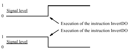
Inversion of a digital output signal.
Syntax
InvertDO
[ Signal ’:=’ ] < variable (VAR) of signaldo > ’;’
IODisable Disable I/O unit
IODisable is used to disable an I/O unit during program execution (only in the S4C system).I/O units are automatically enabled after start-up if they are defined in the system parameters. When required for some reason, I/O units can be disabled or enabled during program execution.
Examples
IODisable "cell1", 5;
Disable I/O unit with name cell1.Wait max. 5 s.
Arguments
IODisable UnitName MaxTime
UnitName Data type: string
The name of the I/O unit to be disabled (with same name as configured).
MaxTime Data type: num
The maximum period of waiting time permitted, expressed in seconds. If this time runs out before the I/O unit has finished the disable steps, the error handler will be called, if there is one, with the error code ERR_IODISABLE. If there is no error handler, the execution will be stopped. To disable an I/O unit takes about 2-5 s.
Program execution
The specified I/O unit starts the disable steps. The instruction is ready when the disable steps are finished. If the MaxTime runs out before the I/O unit has finished the disable steps, a recoverable error will be generated. After disabling an I/O unit, any setting of outputs in this unit will result in an error.
Example
PROC go_home()
VAR num recover_flag :=0;
...
! Start to disable I/O unit cell1
recover_flag := 1;
IODisable "cell1", 0;
! Move to home position
MoveJ home, v1000,fine,tool1;
! Wait until disable of I/O unit cell1 is ready
recover_flag := 2;
IODisable "cell1", 5;
...
ERROR
IF ERRNO = ERR_IODISABLE THEN
IF recover_flag = 1 THEN
TRYNEXT;
ELSEIF recover_flag = 2 THEN
RETRY;
ENDIF
ELSEIF ERRNO = ERR_EXCRTYMAX THEN
ErrWrite "IODisable error", "Not possible to disable I/O unit cell1";
Stop;
ENDIF
ENDPROC
To save cycle time, the I/O unit cell1 is disabled during robot movement to the home position. With the robot at the home position, a test is done to establish whether or not the I/O unit cell1 is fully disabled. After the max. number of retries (5 with a waiting time of 5 s), the robot execution will stop with an error message.The same principle can be used with IOEnable (this will save more cycle time compared with IODisable).
Syntax
IODisable
[ UnitName ’:=’ ] < expression (IN) of string> ’,’
[ MaxTime ’:=’ ] < expression (IN) of num > ’;’
IOEnable Enable I/O unit
IOEnable is used to enable an I/O unit during program execution (only in the S4C system).I/O units are automatically enabled after start-up if they are defined in the system parameters. When required for some reason, I/O units can be disabled or enabled during program execution.
Examples
IOEnable "cell1", 5;
Enable I/O unit with name cell1. Wait max. 5 s.
Arguments
IOEnable UnitName MaxTime
UnitName Data type: string
The name of the I/O unit to be enabled (with same name as configured).
MaxTime Data type: num
The maximum period of waiting time permitted, expressed in seconds. If this time runs out before the I/O unit has finished the enable steps, the error handler will be called, if there is one, with the error code ERR_IOENABLE. If there is no error handler, the execution will be stopped. To enable an I/O unit takes about 2-5 s.
Program execution
The specified I/O unit starts the enable steps. The instruction is ready when the enable steps are finished. If the MaxTime runs out before the I/O unit has finished the enable steps, a recoverable error will be generated. After a sequence of IODisable - IOEnable, all outputs for the current I/O unit will be set to the old values (before IODisable).
Example
IOEnable can also be used to check whether some I/O unit is disconnected for some
reason.
VAR num max_retry:=0;
...
IOEnable "cell1", 0;
SetDO cell1_sig3, 1;
...
ERROR
IF ERRNO = ERR_IOENABLE THEN
IF max_retry < 5 THEN
WaitTime 1;
max_retry := max_retry + 1;
RETRY;
ELSE
RAISE;
ENDIF
ENDIF
Before using signals on the I/O unit cell1, a test is done by trying to enable the I/O unit with timeout after 0 sec. If the test fails, a jump is made to the error handler. In the error handler, the program execution waits for 1 sec. and a new retry is made. After 5 retry attempts the error ERR_IOENABLE is propagated to the caller of this routine.
Syntax
IOEnable
[ UnitName ’:=’ ] < expression (IN) of string> ’,’
[ MaxTime ’:=’ ] < expression (IN) of num > ’;’
ISignalAI Interrupts from analog input signal
ISignalAI (Interrupt Signal Analog Input) is used to order and enable interrupts from an analog input signal.
Example
VAR intnum sig1int;
CONNECT sig1int WITH iroutine1;
ISignalAI \Single, ai1, AIO_BETWEEN, 1.5, 0.5, 0, sig1int;
Orders an interrupt which is to occur the first time the logical value of the analog input signal ai1 is between 0.5 and 1.5. A call is then made to the iroutine1 trap routine.
ISignalAI ai1, AIO_BETWEEN, 1.5, 0.5, 0.1, sig1int;
Orders an interrupt which is to occur each time the logical value of the analog input signal ai1 is between 0.5 and 1.5, and the absolute signal difference com-pared to the stored reference value is bigger than 0.1.
ISignalAI ai1, AIO_OUTSIDE, 1.5, 0.5, 0.1, sig1int;
Orders an interrupt which is to occur each time the logical value of the analog input signal ai1 is lower than 0.5 or higher than 1.5, and the absolute signal dif-ference compared to the stored reference value is bigger than 0.1.
Arguments
ISignalAI [\Single] Signal Condition HighValue LowValue
DeltaValue [\DPos] | [\DNeg] Interrupt
[\Single] Data type: switch
Specifies whether the interrupt is to occur once or cyclically. If the argument Single is set, the interrupt occurs once at the most. If the argu-ment is omitted, an interrupt will occur each time its condition is satisfied.
Signal Data type: signalai
The name of the signal that is to generate interrupts.
Condition Data type: aiotrigg
Specifies how HighValue and LowValue define the condition to be satisfied:
- AIO_ABOVE_HIGH: logical value of the signal is above HighValue
- AIO_BELOW_HIGH: logical value of the signal is below HighValue
- AIO_ABOVE_LOW: logical value of the signal is above LowValue
- AIO_BELOW_LOW: logical value of the signal is below LowValue
- AIO_BETWEEN: logical value of the signal is between LowValue and HighValue
- AIO_OUTSIDE: logical value of the signal is above HighValue or below LowValue
- AIO_ALWAYS: independently of HighValue and LowValue
HighValue Data type: num
High logical value to define the condition.
LowValue Data type: num
Low logical value to define the condition.
DeltaValue Data type: num
Defines the minimum logical signal difference before generation of a new inter-rupt.The actual signal value compared to the stored reference value must be greater than the specified DeltaValue before generation of a new interrupt.
[\DPos] Data type: switch
Specifies that only positive logical signal differences will give new interrupts.
[\DNeg] Data type: switch
Specifies that only negative logical signal differences will give new interrupts. If none of \DPos and \DNeg argument is used, both positive and negative differ-ences will generate new interrupts.
Interrupt Data type: intnum
The interrupt identity. This interrupt should have previously been connected to a trap routine by means of the instruction CONNECT.
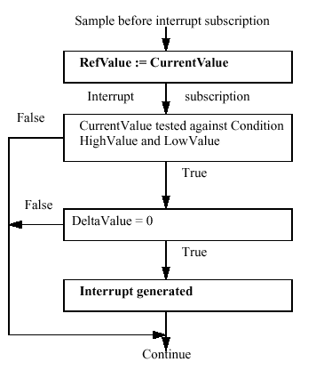
Program execution
When the signal fulfils the specified conditions (both Condition and DeltaValue), a call is made to the corresponding trap routine. When this has been executed, program execution continues from where the interrupt occurred.
Conditions for interrupt generation
Before the interrupt subscription is ordered, each time the signal is sampled, the value of the signal is read, saved, and later used as a reference value for the DeltaValue con-dition. At the interrupt subscription time, if specified DeltaValue = 0 and after the interrupt subscription time always at each time the signal is sampled, its value is then compared to HighValue and LowValue according to Condition and with consideration to DeltaV-alue,to generate or not generate an interrupt. If the new read value satisfies the speci-fied HighValue and LowValue Condition, but its difference compared to the last stored reference value is less or equal to the DeltaValue argument, no interrupt occurs. If the signal difference is not in the specified direction, no interrupts will occur. (argument \DPos or \DNeg). The stored reference value for the DeltaValue condition is updated with a newly read value for later use at any sample, if the following conditions are satisfied:
- Argument Condition with specified HighValue and LowValue (within limits)
- Argument DeltaValue (sufficient signal change in any direction, independently of specified switch \DPos or \DNeg)
The reference value is only updated at the sample time, not at the interrupt subscription time.An interrupt is also generated at the sample for update of the reference value, if the direction of the signal difference is in accordance with the specified argument (any direction, \DPos or \DNeg).When the \Single switch is used, only one interrupt at the most will be generated.If the switch \Single (cyclic interrupt) is not used, at every sample of the signal value a new test is done of the specified conditions (both Condition and DeltaValue) com-pared to the actual signal value and the last stored reference value, to generate or not generate an interrupt.
Condition for interrupt generation at interrupt subscription time
Limitations
The HighValue and LowValue arguments should be in the range: logical maximum value, logical minimum value defined for the signal.
HighValue must be above LowValue.
DeltaValue must be 0 or positive.
The limitations for the interrupt identity are the same as for ISignalDI.
Syntax
ISignalAI
[ ’\’Single’,’]
[ Signal’:=’ ]<variable (VAR) of signalai>’,’
[ Condition’:=’ ]<expression (IN) of aiotrigg>’,’
[ HighValue’:=’ ]<expression (IN) of num>’,’
[ LowValue’:=’ ]<expression (IN) of num>’,’
[ DeltaValue’:=’ ]<expression (IN) of num>
[ ’\’DPos] | [ ’\’DNeg] ’,’
[ Interrupt’:=’ ]<variable (VAR) of intnum>’;’
ISignalAO Interrupts from analog output signal
ISignalAO (Interrupt Signal Analog Output) is used to order and enable interrupts from an analog output signal.
Example
VAR intnum sig1int;
CONNECT sig1int WITH iroutine1;
ISignalAO \Single, ao1, AIO_BETWEEN, 1.5, 0.5, 0, sig1int;
Orders an interrupt which is to occur the first time the logical value of the analog output signal ao1 is between 0.5 and 1.5. A call is then made to the iroutine1 trap routine.
ISignalAO ao1, AIO_BETWEEN, 1.5, 0.5, 0.1, sig1int;
Orders an interrupt which is to occur each time the logical value of the analog output signal ao1 is between 0.5 and 1.5, and the absolute signal difference com-pared to the previous stored reference value is bigger than 0.1.
ISignalAO ao1, AIO_OUTSIDE, 1.5, 0.5, 0.1, sig1int;
Orders an interrupt which is to occur each time the logical value of the analog output signal ao1 is lower than 0.5 or higher than 1.5, and the absolute signal dif-ference compared to the previous stored reference value is bigger than 0.1.
Arguments
ISignalAO [\Single] Signal Condition HighValue LowValue
DeltaValue [\DPos] | [\DNeg] Interrupt
[\Single] Data type: switch
Specifies whether the interrupt is to occur once or cyclically.If the argument Single is set, the interrupt occurs once at the most. If the argu-ment is omitted, an interrupt will occur each time its condition is satisfied.
Signal Data type: signalao
The name of the signal that is to generate interrupts.
Condition Data type: aiotrigg
Specifies how HighValue and LowValue define the condition to be satisfied:
- AIO_ABOVE_HIGH: logical value of the signal is above HighValue
- AIO_BELOW_HIGH: logical value of the signal is below HighValue
- AIO_ABOVE_LOW: logical value of the signal is above LowValue
- AIO_BELOW_LOW: logical value of the signal is below LowValue
- AIO_BETWEEN: logical value of the signal is between LowValue and HighValue
- AIO_OUTSIDE: logical value of the signal is above HighValue or below LowValue
- AIO_ALWAYS: independently of HighValue and LowValue
HighValue Data type: num
High logical value to define the condition.
LowValue Data type: num
Low logical value to define the condition.
DeltaValue Data type: num
Defines the minimum logical signal difference before generation of a new inter-rupt.The actual signal value compared to the previous stored reference value must be greater than the specified DeltaValue before generation of a new inter-rupt.
[\DPos] Data type: switch
Specifies that only positive logical signal differences will give new interrupts.
[\DNeg] Data type: switch
Specifies that only negative logical signal differences will give new interrupts.If neither of the \DPos and \DNeg arguments are used, both positive and negative differences will generate new interrupts.
Interrupt Data type: intnum
The interrupt identity. This interrupt should have previously been connected to a trap routine by means of the instruction CONNECT.
Program execution
See instruction ISignalAI for information about:
- Program execution
- Condition for interrupt generation
- More examples
Same principles are valid for ISignalAO as for ISignalAI.
Limitations
The HighValue and LowValue arguments should be in the range: logical maximum value, logical minimum value, defined for the signal.
HighValue must be above LowValue.
DeltaValue must be 0 or positive.
The limitations for the interrupt identity are the same as for ISignalDO.
Syntax
ISignalAO
[ ’\’Single’,’]
[ Signal’:=’ ]<variable (VAR) of signalao>’,’
[ Condition’:=’ ]<expression (IN) of aiotrigg>’,’
[ HighValue’:=’ ]<expression (IN) of num>’,’
[ LowValue’:=’ ]<expression (IN) of num>’,’
[ DeltaValue’:=’ ]<expression (IN) of num>
[ ’\’DPos] | [ ’\’DNeg] ’,’
[ Interrupt’:=’ ]<variable (VAR) of intnum>’;’
ISignalDI Orders interrupts from a digital input signal
ISignalDI (Interrupt Signal Digital In) is used to order and enable interrupts from a digital input signal. System signals can also generate interrupts.
Examples
VAR intnum sig1int;
CONNECT sig1int WITH iroutine1;
ISignalDI di1,1,sig1int;
Orders an interrupt which is to occur each time the digital input signal di1 is set to 1. A call is then made to the iroutine1 trap routine.
ISignalDI di1,0,sig1int;
Orders an interrupt which is to occur each time the digital input signal di1 is set to 0.
ISignalDI \Single, di1,1,sig1int;
Orders an interrupt which is to occur only the first time the digital input signal di1 is set to 1.
Arguments
ISignalDI [ \Single ] Signal TriggValue Interrupt
[ \Single ] Data type: switch
Specifies whether the interrupt is to occur once or cyclically.If the argument Single is set, the interrupt occurs once at the most. If the argu-ment is omitted, an interrupt will occur each time its condition is satisfied.
Signal Data type: signaldi
The name of the signal that is to generate interrupts.
TriggValue Data type: dionum
The value to which the signal must change for an interrupt to occur. The value is specified as 0 or 1 or as a symbolic value (e.g. high/low). The signal is edge-triggered upon changeover to 0 or 1.
TriggValue 2 or symbolic value edge can be used for generation of interrupts on both positive flank (0 -> 1) and negative flank (1 -> 0).
Interrupt Data type: intnum
The interrupt identity. This should have previously been connected to a trap rou-tineby means of the instruction CONNECT.
Program execution
When the signal assumes the specified value, a call is made to the corresponding trap routine. When this has been executed, program execution continues from where the interrupt occurred. If the signal changes to the specified value before the interrupt is ordered, no interrupt occurs /
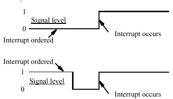
Interrupts from a digital input signal at signal level 1.
Limitations
The same variable for interrupt identity cannot be used more than once, without first deleting it. Interrupts should therefore be handled as shown in one of the alternatives below.
PROC main ( )
VAR intnum sig1int;
CONNECT sig1int WITH iroutine1;
ISignalDI di1, 1, sig1int;
WHILE TRUE DO
:ENDWHILE
ENDPROC
All activation of interrupts is done at the beginning of the program. These instructions are then kept outside the main flow of the program.
PROC main ( )
VAR intnum sig1int;
CONNECT sig1int WITH iroutine1;
ISignalDI di1, 1, sig1int;
:IDelete sig1int;
ENDPROC
The interrupt is deleted at the end of the program, and is then reactivated. It should be noted, in this case, that the interrupt is inactive for a short period.
Syntax
ISignalDI
[ ’\’ Single’,’]
[ Signal ’:=’ ] < variable (VAR) of signaldi > ’,’
[ TriggValue ’:=’ ] < expression (IN) of dionum >’,’
[ Interrupt ’:=’ ] < variable (VAR) of intnum > ’;’
ISignalDO Interrupts from a digital output signal
ISignalDO (Interrupt Signal Digital Out) is used to order and enable interrupts from a digital output signal. System signals can also generate interrupts.
Examples
VAR intnum sig1int;
CONNECT sig1int WITH iroutine1;
ISignalDO do1,1,sig1int;
Orders an interrupt which is to occur each time the digital output signal do1 is set to 1. A call is then made to the iroutine1 trap routine.
ISignalDO do1,0,sig1int;
Orders an interrupt which is to occur each time the digital output signal do1 is
set to 0.
ISignalDO\Single, do1,1,sig1int;
Orders an interrupt which is to occur only the first time the digital output signal
do1 is set to 1.
Arguments
ISignalDO [ \Single ] Signal TriggValue Interrupt
[ \Single ] Data type: switch
Specifies whether the interrupt is to occur once or cyclically.If the argument Single is set, the interrupt occurs once at the most. If the argu-ment is omitted, an interrupt will occur each time its condition is satisfied.
Signal Data type: signaldo
The name of the signal that is to generate interrupts.
TriggValue Data type: dionum
The value to which the signal must change for an interrupt to occur.The value is specified as 0 or 1 or as a symbolic value (e.g. high/low). The signal is edge-triggered upon changeover to 0 or 1. TriggValue 2 or symbolic value edge can be used for generation of interrupts on both positive flank (0 -> 1) and negative flank (1 -> 0).
Interrupt Data type: intnum
The interrupt identity. This should have previously been connected to a trap rou-tine by means of the instruction CONNECT.
Program execution
When the signal assumes the specified value 0 or 1, a call is made to the corresponding trap routine. When this has been executed, program execution continues from where the interrupt occurred. If the signal changes to the specified value before the interrupt is ordered, no interrupt occurs.
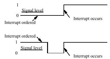
Interrupts from a digital output signal at signal level 1.
Limitations
The same variable for interrupt identity cannot be used more than once, without first deleting it. Interrupts should therefore be handled as shown in one of the alternatives below.
PROC main ( )
VAR intnum sig1int;
CONNECT sig1int WITH iroutine1;
ISignalDO do1, 1, sig1int;
WHILE TRUE DO
::
ENDWHILE
ENDPROC
All activation of interrupts is done at the beginning of the program. These instructions are then kept outside the main flow of the program.
PROC main ( )
VAR intnum sig1int;
CONNECT sig1int WITH iroutine1;
ISignalDO do1, 1, sig1int;
:
:IDelete sig1int;
ENDPROC
The interrupt is deleted at the end of the program, and is then reactivated. It should be noted, in this case, that the interrupt is inactive for a short period.
Syntax
ISignalDO
[ ’\’ Single’,’]
[ Signal ’:=’ ] < variable (VAR) of signaldo > ’,’
[ TriggValue ’:=’ ] < expression (IN) of dionum >’,’
[ Interrupt ’:=’ ] < variable (VAR) of intnum > ’;’
ISleep Deactivates an interrupt
ISleep (Interrupt Sleep) is used to deactivate an individual interrupt temporarily.During the deactivation time, any generated interrupts of the specified type are discarded without any trap execution.
Example
ISleep sig1int;
The interrupt sig1int is deactivated.
Arguments
ISleep Interrupt
Interrupt Data type: intnum
The variable (interrupt identity) of the interrupt.
Program execution
Any generated interrupts of the specified type are discarded without any trap execution, until the interrupt has been re-activated by means of the instruction IWatch. Interrupts which are generated while ISleep is in effect are ignored.
Example
VAR intnum timeint;
CONNECT timeint WITH check_serialch;
ITimer 60, timeint;
.ISleep timeint;
WriteBin ch1, buffer, 30;
IWatch timeint;
.TRAP check_serialch
WriteBin ch1, buffer, 1;
IF ReadBin(ch1\Time:=5) < 0 THEN
TPWrite "The serial communication is broken";
EXIT;
ENDIF
Communication across the ch1 serial channel is monitored by means of interrupts which are generated every 60 seconds. The trap routine checks whether the com-munication is working. When, however, communication is in progress, these interrupts are not permitted.
Error handling
Interrupts which have neither been ordered nor enabled are not permitted. If the inter-rupt number is unknown, the system variable ERRNO will be set to ERR_UNKINO (see "Data types - errnum"). The error can be handled in the error handler.
Syntax
ISleep
[ Interrupt ‘:=’ ] < variable (VAR) of intnum > ‘;’
ITimer Orders a timed interrupt
ITimer (Interrupt Timer) is used to order and enable a timed interrupt.This instruction can be used, for example, to check the status of peripheral equipment once every minute.
Examples
VAR intnum timeint;
CONNECT timeint WITH iroutine1;
ITimer 60, timeint;
Orders an interrupt that is to occur cyclically every 60 seconds. A call is then made to the trap routine iroutine1.
ITimer \Single, 60, timeint;
Orders an interrupt that is to occur once, after 60 seconds.
Arguments
ITimer [ \Single ] Time Interrupt
[ \Single ] Data type: switch
Specifies whether the interrupt is to occur once or cyclically.If the argument Single is set, the interrupt occurs only once. If the argument is omitted, an interrupt will occur each time at the specified time.
Time Data type: num
The amount of time that must lapse before the interrupt occurs.The value is specified in second if Single is set, this time may not be less than 0.05 seconds. The corresponding time for cyclical interrupts is 0.25 seconds.
Interrupt Data type: intnum
The variable (interrupt identity) of the interrupt. This should have previously been connected to a trap routine by means of the instruction CONNECT.
Program execution
The corresponding trap routine is automatically called at a given time following the interrupt order. When this has been executed, program execution continues from where the interrupt occurred. If the interrupt occurs cyclically, a new computation of time is started from when the interrupt occurs.
Example
VAR intnum timeint;
CONNECT timeint WITH check_serialch;
ITimer 60, timeint;
.TRAP check_serialch
WriteBin ch1, buffer, 1;
IF ReadBin(ch1\Time:=5) < 0 THEN
TPWrite "The serial communication is broken";
EXIT;
ENDIF
ENDTRAP
Communication across the ch1 serial channel is monitored by means of interrupts which are generated every 60 seconds. The trap routine checks whether the com-munication is working. If it is not, program execution is interrupted and an error message appears.
Limitations
The same variable for interrupt identity cannot be used more than once, without being first deleted. See Instructions - ISignalDI.
Syntax
ITimer
[ ’\’Single ’,’]
[ Time ’:=’ ] < expression (IN) of num >’,’
[ Interrupt ’:=’ ] < variable (VAR) of intnum > ’;’
IVarValue Orders a variable value interrupt
IVarVal(Interrupt Variable Value) is used to order and enable an interrupt when the value of a variable accessed via the serial sensor interface has been changed. This instruction can be used, for example, to get seam volume or gap values from a seam tracker.
Examples
LOCAL PERS num adtVlt{25}:=[1,1.2,1.4,1.6,1.8,2,2.16667,2.33333,2.5,...];
LOCAL PERS num adptWfd{25}:=[2,2.2,2.4,2.6,2.8,3,3.16667,3.33333,3.5,...];
LOCAL PERS num adptSpd{25}:=10,12,14,16,18,20,21.6667,23.3333,25[,...];
LOCAL CONST num GAP_VARIABLE_NO:=11;
PERS num gap_value;
VAR intnum IntAdap;
PROC main()
! Setup the interrupt. The trap routine AdapTrp will be called
! when the gap variable with number ‘GAP_VARIABLE_NO’ in
! the sensor interface has been changed. The new value will be available
! in the PERS gp_value variable.
CONNECT IntAdap WITH AdapTrp;
IVarValue GAP_VARIABLE_NO, gap_value, IntAdap;
! Start welding
ArcL\On,*,v100,adaptSm,adaptWd,adaptWv,z10,tool\j\Track:=track;
ArcL\On,*,v100,adaptSm,adaptWd,adaptWv,z10,tool\j\Track:=track;
ENDPROC
TRAP AdapTrap
VAR num ArrInd;
!Scale the raw gap value received
ArrInd:=ArrIndx(gap_value);
! Update active welddata PERS variable ‘adaptWd’ with
! new data from the arrays of predefined parameter arrays.
! The scaled gap value is used as index in the voltage, wirefeed and speed arrays.
adaptWd.weld_voltage:=adptVlt{ArrInd};
adaptWd.weld_wirefeed:=adptWfd{ArrInd};
adaptWd.weld_speed:=adptSpd{ArrInd};
!Request a refresh of AW parameters using the new data i adaptWd
ArcRefresh;
ENDTRAP
Arguments
IVarValue VarNo Value, Interrupt
VarNo Data type: num
The number of the variable to be supervised.
Val ue Data type: num
A PERS variable which will hold the new value of Varno.
Interrupt Data type: intnum
The variable (interrupt identity) of the interrupt. This should have previously been connected to a trap routine by means of the instruction CONNECT.
Program execution
The corresponding trap routine is automatically called at a given time following the interrupt order. When this has been executed, program execution continues from where the interrupt occurred.
Limitations
The same variable for interrupt identity cannot be used more than five times, without first being deleted.
Syntax
IVarValue
[ VarNo ’:=’ ] < expression (IN) of num >’,’
[ Value ’:=’ ] < persistent(PERS) of num >’,’
[ Interrupt ’:=’ ] < variable (VAR) of intnum > ’;’
IWatch Activates an interrupt
IWatch (Interrupt Watch) is used to activate an interrupt which was previously ordered but was deactivated with ISleep.
Example
IWatch sig1int;
The interrupt sig1int that was previously deactivated is activated.
Arguments
IWatch Interrupt
Interrupt Data type: intnum
Variable (interrupt identity) of the interrupt.
Program execution
Re-activates interrupts of the specified type once again. However, interrupts generated during the time the ISleep instruction was in effect, are ignored.
Example
VAR intnum sig1int;
CONNECT sig1int WITH iroutine1;
ISignalDI di1,1,sig1int;
.ISleep sig1int;
weldpart1;
IWatch sig1int;
During execution of the weldpart1 routine, no interrupts are permitted from the signal di1.
Error handling
Interrupts which have not been ordered are not permitted. If the interrupt number is unknown, the system variable ERRNO is set to ERR_UNKINO (see "Date types - err-num"). The error can be handled in the error handler.
Syntax
IWatch
[ Interrupt ‘:=’ ] < variable (VAR) of intnum > ‘;’
label Line name
Label is used to name a line in the program. Using the GOTO instruction, this name can then be used to move program execution.
Example
GOTO next;
.next:
Program execution continues with the instruction following next.
Arguments
Label:
Label Identifier
The name you wish to give the line.
Program execution
Nothing happens when you execute this instruction.
Limitations
The label must not be the same as
- any other label within the same routine,
- any data name within the same routine.
A label hides global data and routines with the same name within the routine it is located in.
Syntax
(EBNF)
<identifier>’:’
Load Load a program module during execution
Load is used to load a program module into the program memory during execution. The loaded program module will be added to the already existing modules in the pro-gram memory. A program or system module can be loaded in static (default) or dynamic mode:

Both static and dynamic loaded modules can be unloaded by the instruction UnLoad.
Example
Load \Dynamic, ram1disk \File:="PART_A.MOD";Load the program module PART_A.MOD from the ram1disk into the program memory. ( ram1disk is a predefined string constant "ram1disk:"). Load program module in dynamic mode.
Arguments
Load [\Dynamic] FilePath [\File]
[\Dynamic] Data type: switch
The switch enables load of a program module in dynamic mode. Otherwise the load is in static mode.
FilePath Data type: string
The file path and the file name to the file that will be loaded into the program memory. The file name shall be excluded when the argument \File is used.
[\File] Data type: string
When the file name is excluded in the argument FilePath then it must be defined with this argument.
Program execution
Program execution waits for the program module to finish loading before proceeding with the next instruction. To obtain a good program structure, that is easy to understand and maintain, all loading and unloading of program modules should be done from the main module which is always present in the program memory during execution.After the program module is loaded it will be linked and initialised. The initialisation of the loaded module sets all variables at module level to their init values. Unresolved references will be accepted if the system parameter for Tasks is set (BindRef = NO). However, when the program is started or the teach pendant function Program/File/ Check is used, no check for unresolved references will be done if the parameter Bind-Ref = NO. There will be a run time error on execution of an unresolved reference.
Examples
Load \Dynamic, "ram1disk:DOORDIR/DOOR1.MOD";
Loads the program module DOOR1.MOD from the ram1disk at the directory
DOORDIR into the program memory. The program module is loaded in dynamic mode.
Load \Dynamic, "ram1disk:" \File:="DOORDIR/DOOR1.MOD";
Same as above but another syntax.
Load "ram1disk:" \File:="DOORDIR/DOOR1.MOD";
Same as the two examples above but the module is loaded in static mode.
Limitations
Loading a program module that contains a main routine is not allowed.Avoid ongoing robot movements during the loading.Avoid using the floppy disk for loading since reading from the floppy drive is very time consuming.
Error handling
If the file in the Load instructions cannot be found, then the system variable ERRNO is set to ERR_FILNOTFND. If the module already is loaded into the program memory then the system variable ERRNO is set to ERR_LOADED (see "Data types - errnum").The errors above can be handled in an error handler.
Syntax
Load
[‘\’Dynamic ‘,’]
[FilePath’:=’]<expression (IN) of string>
[’\’File’:=’ <expression (IN) of string>]’;’
MechUnitLoad Defines a payload for a mechanical unit
MechUnitLoad is used to define a payload for an external mechanical unit.(The payload for the robot is defined with instruction GripLoad) This instruction should be used for all mechanical units with dynamic model in servo to achieve the best motion performance. The MechUnitLoad instruction should always be executed after execution of the instruction ActUnit.
A mechanical unit named IRBP_L of type IRBP L.
ActUnit IRBP_L;
MechUnitLoad IRBP_L, 1, load0;
Activate mechanical unit IRBP_L and define the payload load0 corresponding to no load (at all) mounted on axis 1.
ActUnit IRBP_L;
MechUnitLoad IRBP_L, 1, fixture1;
Activate mechanical unit IRBP_L and define the payload fixture1 corresponding to fixture fixture1 mounted on axis 1.
ActUnit IRBP_L;
MechUnitLoad IRBP_L, 1, workpiece1;
Activate mechanical unit IRBP_L and define the payload workpiece1 corre-sponding to fixture and work piece named workpiece1 mounted on axis 1.
Arguments
MechUnitLoad MechUnit AxisNo Load
MechUnit (Mechanical Unit) Data type: mecunit
The name of the mechanical unit.
AxisNo (Axis Number) Data type: num
The axis number, within the mechanical unit, that holds the load.
Load Data type: loaddata
The load data that describes the current payload to be defined.
Program execution
After execution of MechUnitLoad, when the robot and external axes have come to a standstill, the specified load is defined for the specified mechanical unit and axis. This means that the payload is controlled and monitored by the control system.The default payload at cold start-up, for a certain mechanical unit type, is the prede-finedmaximal payload for this mechanical unit type.When some other payload is used, the actual payload for the mechanical unit and axis should be redefined with this instruction. This should always be done after activation of the mechanical unit. The defined payload will survive a power failure restart.The defined payload will also survive a restart of the program after manual activation of some other mechanical units from the jogging window.
Payload mounted on the end-effector of a mechanical unit.
Example
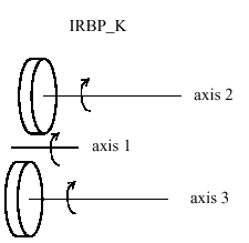
MoveL homeside1, v1000, fine, gun1;
ActUnit IRBP_K;
The whole mechanical unit IRBP_K is activated.
MechUnitLoad IRBP_K, 2, workpiece1;
Defines payload workpiece1 on the mechanical unit IRBP_K axis 2.
MechUnitLoad IRBP_K, 3, workpiece2;
Defines payload workpiece2 on the mechanical unit IRBP_K axis 3.
MoveL homeside2, v1000, fine, gun1
The axes of the mechanical unit IRBP_K move to the switch position homeside2 with mounted payload on both axes 2 and 3.
Limitations
The movement instruction previous to this instruction should be terminated with a stop point in order to make a restart in this instruction possible following a power failure.
Syntax
MechUnitLoad
[MechUnit ’:=’ ] < variable (VAR) of mecunit> ’,’
[AxisNo ‘:=’ ] <expression (IN) of num ‘,’
[ Load ’:=’ ] < persistent (PERS) of loaddata > ’;’
MoveCSync Moves the robot circularly and executes a RAPID procedure
MoveCSync ( Move Circular Synchronously) is used to move the tool centre point (TCP) circularly to a given destination. The specified RAPID procedure is executed at the mid-dle of the corner path in the destination point. During the movement, the orientation nor-mally remains unchanged relative to the circle.
Examples
MoveCSync p1, p2, v500, z30, tool2, "proc1";
The TCP of the tool, tool2, is moved circularly to the position p2, with speed data v500 and zone data z30. The circle is defined from the start position, the circle point p1 and the destination point p2. Procedure proc1 is executed in the middle of the corner path at p2.
Arguments
MoveCSync CirPoint ToPoint Speed [ \T ] Zone Tool [\WObj ]
ProcName
CirPoint Data type: robtarget
The circle point of the robot. The circle point is a position on the circle between the start point and the destination point. To obtain the best accuracy, it should be placed about halfway between the start and destination points. If it is placed too close to the start or destination point, the robot may give a warning. The circle point is defined as a named position or stored directly in the instruction (marked with an * in the instruction). The position of the external axes are not used.
ToPoi nt Data type: robtarget
The destination point of the robot and external axes. It is defined as a named position or stored directly in the instruction (marked with an * in the instruction).
Speed Data type: speeddata
The speed data that applies to movements. Speed data defines the velocity of the TCP, the tool reorientation and external axes.
[ \T ] (Time) Data type: num
This argument is used to specify the total time in seconds during which the robot and external axes move. It is then substituted for the corresponding speed data.
Zone Data type: zonedata
Zone data for the movement. Zone data describes the size of the generated corner path.
Tool Data type: tooldata
The tool in use when the robot moves. The tool centre point is the point that is moved to the specified destination point.
[ \WObj] (Work Object) Data type: wobjdata
The work object (object coordinate system) to which the robot position in the instruction is related. This argument can be omitted, and if it is, the position is related to the world coor-dinate system. If, on the other hand, a stationary TCP or coordinated external axes are used, this argument must be specified.
ProcName (Procedure Name) Data type: string
Name of the RAPID procedure to be executed at the middle of the corner path in the destination point.
Program execution
See the instruction MoveC for more information about circular movements.The specified RAPID procedure is executed when the TCP reaches the middle of the corner path in the destination point of the MoveCSync instruction.
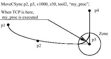
Execution of user-defined RAPID procedure at the middle of the corner path.
For stop points, we recommend the use of "normal" programming sequence with MoveC + other RAPID instructions in sequence.Execution of the specified RAPID procedure in different execution modes: Execution mode: Execution of RAPID procedure: Continuously or Cycle According to this description Forward step In the stop point Backward step Not at all
Limitation
General limitations according to instruction MoveC. Switching execution mode after program stop from continuously or cycle to stepwise forward or backward results in an error. This error tells the user that the mode switch can result in missed execution of a RAPID procedure in the queue for execution on the path. This error can be avoided if the program is stopped with StopInstr before the mode switch.
Instruction MoveCSync cannot be used on TRAP level.The specified RAPID procedure cannot be tested with stepwise execution.
Syntax
MoveCSync
[ CirPoint ’:=’ ] < expression (IN) of robtarget > ’,’
[ ToPoint ’:=’ ] < expression (IN) of robtarget > ’,’
[ Speed ’:=’ ] < expression (IN) of speeddata >
[ ’\’ T ’:=’ < expression (IN) of num > ] ’,’
[ Zone ’:=’ ] < expression (IN) of zonedata > ’,’
[ Tool ’:=’ ] < persistent (PERS) of tooldata >
[ ’\’ WObj ’:=’ < persistent (PERS) of wobjdata > ] ’,’
[ ProcName ‘:=’ ] < expression (IN) of string > ] ’;’
MoveAbsJ Moves the robot to an absolute joint position
MoveAbsJ (Move Absolute Joint) is used to move the robot to an absolute position, defined in axes positions.
This instruction need only be used when:
- the end point is a singular point
- for ambiguous positions on the IRB 6400C, e.g. for movements with the tool over the robot.
The final position of the robot, during a movement with MoveAbsJ, is neither affected by the given tool and work object, nor by active program displacement. However, the robot uses these data to calculating the load, TCP velocity, and the corner path. The same tools can be used as in adjacent movement instructions. The robot and external axes move to the destination position along a non-linear path. All axes reach the destination position at the same time.
Examples
MoveAbsJ p50, v1000, z50, tool2;
The robot with the tool tool2 is moved along a non-linear path to the absolute axis position, p50, with velocity data v1000 and zone data z50.
MoveAbsJ *, v1000\T:=5, fine, grip3;
The robot with the tool grip3, is moved along a non-linear path to a stop point which is stored as an absolute axis position in the instruction (marked with an *).
The entire movement takes 5 s.
Arguments
MoveAbsJ [ \Conc ] ToJointPos [\NoEOffs] Speed [ \V ] | [ \T ]
Zone [ \Z ] Tool [ \WObj ]
[ \Conc ] (Concurrent) Data type: switch
Subsequent instructions are executed while the robot is moving. The argument is used to shorten the cycle time when, for example, communicating with external equipment, if synchronisation is not required.Using the argument \Conc, the number of movement instructions in succession is limited to 5. In a program section that includes StorePath-RestoPath, move-ment instructions with the argument \Conc are not permitted.If this argument is omitted and the ToPoint is not a stop point, the subsequent instruction is executed some time before the robot has reached the programmed zone.
ToJointPos (To Joint Position) Data type: jointtarget
The destination absolute joint position of the robot and external axes. It is defined as a named position or stored directly in the instruction (marked with an * in the instruction).
[ \NoEOffs ] (No External Offsets) Data type: switch
If the argument NoEOffs is set, then the movement with MoveAbsJ is not affected by active offsets for external axes.
Speed Data type: speeddata
The speed data that applies to movements. Speed data defines the velocity of the tool centre point, the tool reorientation and external axes.
[ \V ] (Velocity) Data type: num
This argument is used to specify the velocity of the TCP in mm/s directly in the instruction. It is then substituted for the corresponding velocity specified in the speed data.
[ \T ] (Time) Data type: num
This argument is used to specify the total time in seconds during which the robot moves. It is then substituted for the corresponding speed data.
Zone Data type: zonedata
Zone data for the movement. Zone data describes the size of the generated corner path.
[ \Z ] (Zone) Data type: num
This argument is used to specify the position accuracy of the robot TCP directly in the instruction. The length of the corner path is given in mm, which is substi-tuted for the corresponding zone specified in the zone data.
Tool Data type: tooldata
The tool in use during the movement. The position of the TCP and the load on the tool are defined in the tool data. The TCP position is used to decide the velocity and the corner path for the movement.
[ \WObj] (Work Object) Data type: wobjdata
The work object used during the movement.This argument can be omitted if the tool is held by the robot. However, if the robot holds the work object, i.e. the tool is stationary, or with coordinated exter-nal axes, then the argument must be specified. In the case of a stationary tool or coordinated external axes, the data used by the system to decide the velocity and the corner path for the movement, is defined in the work object.
Program execution
A movement with MoveAbsJ is not affected by active program displacement and if executed with switch \NoEOffs, there will be no offset for external axes. Without switch \NoEOffs, the external axes in the destination target are affected by active offset for external axes. The tool is moved to the destination absolute joint position with interpolation of the axis angles. This means that each axis is moved with constant axis velocity and that all axes reach the destination joint position at the same time, which results in a non-linear path. Generally speaking, the TCP is moved at approximate programmed velocity. The tool is reoriented and the external axes are moved at the same time as the TCP moves. If the programmed velocity for reorientation, or for the external axes, cannot be attained, the velocity of the TCP will be reduced. A corner path is usually generated when movement is transferred to the next section of the path. If a stop point is specified in the zone data, program execution only continues when the robot and external axes have reached the appropriate joint position.
Examples
MoveAbsJ *, v2000\V:=2200, z40 \Z:=45, grip3;
The tool, grip3, is moved along a non-linear path to a absolute joint position stored in the instruction. The movement is carried out with data set to v2000 and z40, the velocity and zone size of the TCP are 2200 mm/s and 45 mm respec-tively.
MoveAbsJ \Conc, *, v2000, z40, grip3;
The tool, grip3, is moved along a non-linear path to a absolute joint position stored in the instruction. Subsequent logical instructions are executed while the robot moves.
MoveAbsJ \Conc, * \NoEOffs, v2000, z40, grip3;
Same movement as above but the movement is not affected by active offsets for
external axes.
GripLoad obj_mass;
MoveAbsJ start, v2000, z40, grip3 \WObj:= obj;
The robot moves the work object obj in relation to the fixed tool grip3 along a non-linear path to an absolute axis position start.
Error handling
When running the program, a check is made that the arguments Tool and \WObj do not contain contradictory data with regard to a movable or a stationary tool respectively.
Limitations
In order to be able to run backwards with the instruction MoveAbsJ involved, and avoiding problems with singular points or ambiguous areas, it is essential that the sub-sequent instructions fulfil certain requirements, as follows .
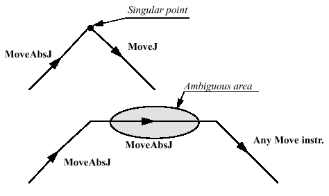
Limitation for backward execution with MoveAbsJ.
Syntax
MoveAbsJ
[ ’\’ Conc ’,’ ]
[ ToJointPos ’:=’ ] < expression (IN) of jointtarget >
[ ’\’ NoEoffs ] ’,’
[ Speed ’:=’ ] < expression (IN) of speeddata >
[ ’\’ V ’:=’ < expression (IN) of num > ]
| [ ’\’ T ’:=’ < expression (IN) of num > ] ’,’
[Zone ’:=’ ] < expression (IN) of zonedata >
[ ’\’ Z ‘:=’ < expression (IN) of num > ] ’,’
[ Tool ’:=’ ] < persistent (PERS) of tooldata >
[ ’\’ WObj ’:=’ < persistent (PERS) of wobjdata > ] ’;’
MoveC Moves the robot circularly
MoveC is used to move the tool centre point (TCP) circularly to a given destination.During the movement, the orientation normally remains unchanged relative to the circle.
Examples
MoveC p1, p2, v500, z30, tool2;
The TCP of the tool, tool2, is moved circularly to the position p2, with speed data v500 and zone data z30. The circle is defined from the start position, the circle point p1 and the destination point p2.
MoveC *, *, v500 \T:=5, fine, grip3;
The TCP of the tool, grip3, is moved circularly to a fine point stored in the instruction (marked by the second *). The circle point is also stored in the instruction (marked by the first *). The complete movement takes 5 seconds.
MoveL p1, v500, fine, tool1;
MoveC p2, p3, v500, z20, tool1;
MoveC p4, p1, v500, fine, tool1;
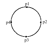
A complete circle is performed by two MoveC instructions.
Arguments
MoveC [ \Conc ] CirPoint ToPoint Speed [ \V ] | [ \T ] Zone [ \Z]
Tool [ \WObj ] [ \Corr ]
[ \Conc ] (Concurrent) Data type: switch Subsequent instructions are executed at once. This argument is used to shorten the cycle time when, for example, communicating with external equipment, if synchronisation is not required. Using the argument \Conc, the number of movement instructions in succession is limited to 5. In a program section that includes StorePath-RestoPath, movement instructions with the argument \Conc are not permitted. If this argument is omitted, and the ToPoint is not a Stop point the subsequent instruction is executed some time before the robot has reached the programmed zone.
CirPoint Data type: robtarget
The circle point of the robot. The circle point is a position on the circle between the start point and the destination point. To obtain the best accuracy, it should be placed about halfway between the start and destination points. If it is placed too close to the start or destination point, the robot may give a warning. The circle point is defined as a named position or stored directly in the instruction (marked with an * in the instruction). The position of the external axes are not used. ToPoi nt Data type: robtarget The destination point of the robot and external axes. It is defined as a named position or stored directly in the instruction (marked with an * in the instruction).
Speed Data type: speeddata
The speed data that applies to movements. Speed data defines the velocity of the TCP, the tool reorientation and external axes.
[ \V ] (Velocity) Data type: num
This argument is used to specify the velocity of the TCP in mm/s directly in the instruction. It is then substituted for the corresponding velocity specified in the speed data.
[ \T ] (Time) Data type: num
This argument is used to specify the total time in seconds during which the robot and external axes move. It is then substituted for the corresponding speed data.
Zone Data type: zonedata
Zone data for the movement. Zone data describes the size of the generated corner path.
[ \Z ] (Zone) Data type: num
This argument is used to specify the position accuracy of the robot TCP directly in the instruction. The length of the corner path is given in mm, which is substituted for the corresponding zone specified in the zone data.
Tool Data type: tooldata
The tool in use when the robot moves. The tool centre point is the point that is moved to the specified destination point.
[ \WObj] (Work Object) Data type: wobjdata
The work object (object coordinate system) to which the robot position in the instruction is related.
This argument can be omitted, and if it is, the position is related to the world coordinate system. If, on the other hand, a stationary TCP or coordinated external axes are used, this argument must be specified in order for a circle relative to the work object to be executed.
[ \Corr] (Correction) Data type: switch
Correction data written to a corrections entry by the instruction CorrWrite will be added to the path and destination position, if this argument is present.
Program execution
The robot and external units are moved to the destination point as follows:
- The TCP of the tool is moved circularly at constant programmed velocity.
- The tool is reoriented at a constant velocity, from the orientation at the start position to the orientation at the destination point.
- The reorientation is performed relative to the circular path. Thus, if the orientation relative to the path is the same at the start and the destination points, the relative orientation remains unchanged during the movement (see Figure 3).
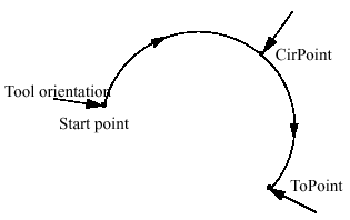
Tool orientation during circular movement.
- The orientation at the circle point is not critical; it is only used to distinguish between two possible directions of reorientation. The accuracy of the reorientation along the path depends only on the orientation at the start and destination points.
- Uncoordinated external axes are executed at constant velocity in order for them to arrive at the destination point at the same time as the robot axes. The position in the circle position is not used. If it is not possible to attain the programmed velocity for the reorientation or for the external axes, the velocity of the TCP will be reduced.
A corner path is usually generated when movement is transferred to the next section of a path. If a stop point is specified in the zone data, program execution only continues when the robot and external axes have reached the appropriate position.
Examples
MoveC *, *, v500 \V:=550, z40 \Z:=45, grip3;
The TCP of the tool, grip3, is moved circularly to a position stored in the instruction. The movement is carried out with data set to v500 and z40; the velocity and zone size of the TCP are 550 mm/s and 45 mm respectively.
MoveC \Conc, *, *, v500, z40, grip3;
The TCP of the tool, grip3, is moved circularly to a position stored in the instruction. The circle point is also stored in the instruction. Subsequent logical instructions are executed while the robot moves.
MoveC cir1, p15, v500, z40, grip3 \WObj:=fixture;
The TCP of the tool, grip3, is moved circularly to a position, p15, via the circle point cir1. These positions are specified in the object coordinate system for fixture.
Limitations
A change of execution mode from forward to backward or vice versa, while the robot is stopped on a circular path, is not permitted and will result in an error message. The instruction MoveC (or any other instruction including circular movement) should never be started from the beginning, with TCP between the circle point and the end point. Otherwise the robot will not take the programmed path (positioning around the circular path in another direction compared with that programmed).Make sure that the robot can reach the circle point during program execution and divide the circle segment if necessary.
Syntax
MoveC
[ ’\’ Conc ’,’ ]
[ CirPoint ’:=’ ] < expression (IN) of robtarget > ’,’
[ ToPoint ’:=’ ] < expression (IN) of robtarget > ’,’
[ Speed ’:=’ ] < expression (IN) of speeddata >
[ ’\’ V ’:=’ < expression (IN) of num > ]
| [ ’\’ T ’:=’ < expression (IN) of num > ] ’,’
[Zone ’:=’ ] < expression (IN) of zonedata >
[ ’\’ Z ’:=’ < expression (IN) of num > ] ’,’
[ Tool ’:=’ 7] < persistent (PERS) of tooldata >
[ ’\’ WObj ’:=’ < persistent (PERS) of wobjdata > ]
[ ’\’ Corr ]’;’
MoveCDO Moves the robot circularly and sets digital output in the corner
MoveCDO (Move Circular Digital Output) is used to move the tool centre point (TCP) circularly to a given destination. The specified digital output is set/reset in the middle of the corner path at the destination point. During the movement, the orientation normally remains unchanged relative to the circle.
Examples
MoveCDO p1, p2, v500, z30, tool2, do1,1;
The TCP of the tool, tool2, is moved circularly to the position p2, with speed data v500 and zone data z30. The circle is defined from the start position, the circle point p1 and the destination point p2. Output do1 is set in the middle of the corner path at p2.
Arguments
MoveCDO CirPoint ToPoint Speed [ \T ] Zone Tool [\WObj ]
Signal Value
CirPoint Data type: robtarget
The circle point of the robot. The circle point is a position on the circle between the start point and the destination point. To obtain the best accuracy, it should be placed about halfway between the start and destination points. If it is placed too close to the start or destination point, the robot may give a warning. The circle point is defined as a named position or stored directly in the instruction (marked with an * in the instruction). The position of the external axes are not used.
ToPoi nt Data type: robtarget
The destination point of the robot and external axes. It is defined as a named position or stored directly in the instruction (marked with an * in the instruction).
Speed Data type: speeddata
The speed data that applies to movements. Speed data defines the velocity of the TCP, the tool reorientation and external axes.
[ \T ] (Time) Data type: num
This argument is used to specify the total time in seconds during which the robot and external axes move. It is then substituted for the corresponding speed data.
Zone Data type: zonedata
Zone data for the movement. Zone data describes the size of the generated corner path.
Tool Data type: tooldata
The tool in use when the robot moves. The tool centre point is the point that is moved to the specified destination point.
[ \WObj] (Work Object) Data type: wobjdata
The work object (object coordinate system) to which the robot position in the instruction is related. This argument can be omitted, and if it is, the position is related to the world coor-dinate system. If, on the other hand, a stationary TCP or coordinated external axes are used, this argument must be specified in order for a circle relative to the work object to be executed.
Signal Data type: signaldo
The name of the digital output signal to be changed.
Val ue Data type: dionum
The desired value of signal (0 or 1).
Program execution
See the instruction MoveC for more information about circular movement.
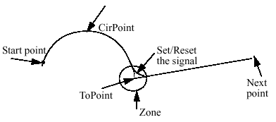
Set/Reset of digital output signal in the corner path with MoveCDO.For stop points, we recommend the use of "normal" programming sequence with MoveC + SetDO. But when using stop point in instruction MoveCDO, the digital output signal is set/reset when the robot reaches the stop point.The specified I/O signal is set/reset in execution mode continuously and stepwise for-ward but not in stepwise backward.
Limitations
General limitations according to instruction MoveC.
Syntax
MoveCDO
[ CirPoint ’:=’ ] < expression (IN) of robtarget > ’,’
[ ToPoint ’:=’ ] < expression (IN) of robtarget > ’,’
[ Speed ’:=’ ] < expression (IN) of speeddata >
[ ’\’ T ’:=’ < expression (IN) of num > ] ’,’
[ Zone ’:=’ ] < expression (IN) of zonedata > ’,’
[ Tool ’:=’ ] < persistent (PERS) of tooldata >
[ ’\’ WObj ’:=’ < persistent (PERS) of wobjdata > ] ’,’
[ Signal ’:=’ ] < variable (VAR) of signaldo>] ‘,’
[ Value ‘:=’ ] < expression (IN) of dionum > ] ’;’
MoveJDO Moves the robot by joint movement and sets digital output in the corner
MoveJDO (Move Joint Digital Output) is used to move the robot quickly from one point to another when that movement does not have to be in a straight line. The speci-fied digital output signal is set/reset at the middle of the corner path. The robot and external axes move to the destination position along a non-linear path. All axes reach the destination position at the same time.
Examples
MoveJDO p1, vmax, z30, tool2, do1, 1;
The tool centre point (TCP) of the tool, tool2, is moved along a non-linear path to the position, p1, with speed data vmax and zone data z30. Output do1 is set in the middle of the corner path at p1.
Arguments
MoveJDO ToPoint Speed [ \T ] Zone Tool
[ \WObj ] Signal Value
ToPoi nt Data type: robtarget
The destination point of the robot and external axes. It is defined as a named position or stored directly in the instruction (marked with an * in the instruction).
Speed Data type: speeddata
The speed data that applies to movements. Speed data defines the velocity of the tool centre point, the tool reorientation and external axes.
[ \T ] (Time) Data type: num
This argument is used to specify the total time in seconds during which the robot moves. It is then substituted for the corresponding speed data.
Zone Data type: zonedata
Zone data for the movement. Zone data describes the size of the generated corner path.
Tool Data type: tooldata
The tool in use when the robot moves. The tool centre point is the point moved to the specified destination point.
[ \WObj] (Work Object) Data type: wobjdata
The work object (coordinate system) to which the robot position in the instruction is related. This argument can be omitted, and if it is, the position is related to the world coor-dinate system. If, on the other hand, a stationary TCP or coordinated external axes are used, this argument must be specified.
Signal Data type: signaldo
The name of the digital output signal to be changed.
Val ue Data type: dionum
The desired value of signal (0 or 1).
Program execution
See the instruction MoveJ for more information about joint movement.The digital output signal is set/reset in the middle of the corner path for flying points,

Reset of digital output signal in the corner path with MoveJDO.
For stop points, we recommend the use of "normal" programming sequence with MoveJ + SetDO. But when using stop point in instruction MoveJDO, the digital output signal is set/reset when the robot reaches the stop point. The specified I/O signal is set/reset in execution mode continuously and stepwise for-ward but not in stepwise backward.
Syntax
MoveJDO
[ ToPoint ’:=’ ] < expression (IN) of robtarget > ’,’
[ Speed ’:=’ ] < expression (IN) of speeddata >
[ ’\’ T ’:=’ < expression (IN) of num > ] ’,’
[ Zone ’:=’ ] < expression (IN) of zonedata > ’,’
[ Tool ’:=’ ] < persistent (PERS) of tooldata >
[ ’\’ WObj ’:=’ < persistent (PERS) of wobjdata > ] ’,’
[ Signal ’:=’ ] < variable (VAR) of signaldo>] ‘,’
[ Value ‘:=’ ] < expression (IN) of dionum > ] ’;’
MoveJ Moves the robot by joint movement
MoveJ is used to move the robot quickly from one point to another when that move-ment does not have to be in a straight line. The robot and external axes move to the destination position along a non-linear path. All axes reach the destination position at the same time.
Examples
MoveJ p1, vmax, z30, tool2;
The tool centre point (TCP) of the tool, tool2, is moved along a non-linear path to the position, p1, with speed data vmax and zone data z30.
MoveJ *, vmax \T:=5, fine, grip3;
The TCP of the tool, grip3, is moved along a non-linear path to a stop point stored in the instruction (marked with an *). The entire movement takes 5 sec-onds.
Arguments
MoveJ [ \Conc ] ToPoint Speed [ \V ] | [ \T ] Zone [ \Z ] Tool
[ \WObj ]
[ \Conc ] (Concurrent) Data type: switch
Subsequent instructions are executed while the robot is moving. The argument is used to shorten the cycle time when, for example, communicating with external equipment, if synchronisation is not required. Using the argument \Conc, the number of movement instructions in succession is limited to 5. In a program section that includes StorePath-RestoPath, move-ment instructions with the argument \Conc are not permitted. If this argument is omitted and the ToPoint is not a stop point, the subsequent instruction is executed some time before the robot has reached the programmed zone.
ToPoi nt Data type: robtarget
The destination point of the robot and external axes. It is defined as a named position or stored directly in the instruction (marked with an * in the instruction).
Speed Data type: speeddata
The speed data that applies to movements. Speed data defines the velocity of the tool centre point, the tool reorientation and external axes.
[ \V ] (Velocity) Data type: num
This argument is used to specify the velocity of the TCP in mm/s directly in the instruction. It is then substituted for the corresponding velocity specified in the speed data.
[ \T ] (Time) Data type: num
This argument is used to specify the total time in seconds during which the robot moves. It is then substituted for the corresponding speed data.
Zone Data type: zonedata
Zone data for the movement. Zone data describes the size of the generated corner path.
[ \Z ] (Zone) Data type: num
This argument is used to specify the position accuracy of the robot TCP directly in the instruction. The length of the corner path is given in mm, which is substi-tuted for the corresponding zone specified in the zone data.
Tool Data type: tooldata
The tool in use when the robot moves. The tool centre point is the point moved to the specified destination point.
[ \WObj] (Work Object) Data type: wobjdata
The work object (coordinate system) to which the robot position in the instruction is related. This argument can be omitted, and if it is, the position is related to the world coor-dinate system. If, on the other hand, a stationary TCP or coordinated external axes are used, this argument must be specified.
Program execution
The tool centre point is moved to the destination point with interpolation of the axis angles. This means that each axis is moved with constant axis velocity and that all axes reach the destination point at the same time, which results in a non-linear path. Generally speaking, the TCP is moved at the approximate programmed velocity (regardless of whether or not the external axes are coordinated). The tool is reoriented and the external axes are moved at the same time as the TCP moves. If the programmed velocity for reorientation, or for the external axes, cannot be attained, the velocity of the TCP will be reduced.A corner path is usually generated when movement is transferred to the next section of the path. If a stop point is specified in the zone data, program execution only continues when the robot and external axes have reached the appropriate position.
Examples
MoveJ *, v2000\V:=2200, z40 \Z:=45, grip3;
The TCP of the tool, grip3, is moved along a non-linear path to a position stored in the instruction. The movement is carried out with data set to v2000 and z40; the velocity and zone size of the TCP are 2200 mm/s and 45 mm respectively.
MoveJ \Conc, *, v2000, z40, grip3;
The TCP of the tool, grip3, is moved along a non-linear path to a position stored in the instruction. Subsequent logical instructions are executed while the robot moves.
MoveJ start, v2000, z40, grip3 \WObj:=fixture;
The TCP of the tool, grip3, is moved along a non-linear path to a position, start. This position is specified in the object coordinate system for fixture.
Syntax
MoveJ
[ ’\’ Conc ’,’ ]
[ ToPoint ’:=’ ] < expression (IN) of robtarget > ’,’
[ Speed ’:=’ ] < expression (IN) of speeddata >
[ ’\’ V ’:=’ < expression (IN) of num > ]
| [ ’\’ T ’:=’ < expression (IN) of num > ] ’,’
[Zone ’:=’ ] < expression (IN) of zonedata >
[ ’\’ Z ‘:=’ < expression (IN) of num > ] ’,’
[ Tool ’:=’ ] < persistent (PERS) of tooldata >
[ ’\’ WObj ’:=’ < persistent (PERS) of wobjdata > ] ’;’
MoveLDO Moves the robot linearly and sets digital output in the corner
MoveLDO (Move Linearly Digital Output) is used to move the tool centre point (TCP) linearly to a given destination. The specified digital output signal is set/reset at the mid-dle of the corner path. When the TCP is to remain stationary, this instruction can also be used to reorient the tool.
Example
MoveLDO p1, v1000, z30, tool2, do1,1;
The TCP of the tool, tool2, is moved linearly to the position p1, with speed data v1000 and zone data z30. Output do1 is set in the middle of the corner path at p1.
Arguments
MoveLDO ToPoint Speed [ \T ] Zone Tool
[ \WObj ] Signal Value
ToPoi nt Data type: robtarget
The destination point of the robot and external axes. It is defined as a named position or stored directly in the instruction (marked with an * in the instruction).
Speed Data type: speeddata
The speed data that applies to movements. Speed data defines the velocity for the tool centre point, the tool reorientation and external axes.
[ \T ] (Time) Data type: num
This argument is used to specify the total time in seconds during which the robot moves. It is then substituted for the corresponding speed data.
Zone Data type: zonedata
Zone data for the movement. Zone data describes the size of the generated corner path.
Tool Data type: tooldata
The tool in use when the robot moves. The tool centre point is the point moved to the specified destination position. [ \WObj] (Work Object) Data type: wobjdata
The work object (coordinate system) to which the robot position in the instruction is related. This argument can be omitted, and if it is, the position is related to the world coor-dinate system. If, on the other hand, a stationary TCP or coordinated external axes are used, this argument must be specified.
Signal Data type: signaldo
The name of the digital output signal to be changed.
Val ue Data type: dionum
The desired value of signal (0 or 1).
Program execution
See the instruction MoveL for more information about linear movements.The digital output signal is set/reset in the middle of the corner path for flying points,
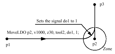
Set/Reset of digital output signal in the corner path with MoveLDO.
For stop points, we recommend the use of "normal" programming sequence with MoveL + SetDO. But when using stop point in instruction MoveLDO, the digital output signal is set/reset when the robot reaches the stop point. The specified I/O signal is set/reset in execution mode continuously and stepwise for-ward but not in stepwise backward.
Syntax
MoveLDO
[ ToPoint ’:=’ ] < expression (IN) of robtarget > ’,’
[ Speed ’:=’ ] < expression (IN) of speeddata >
[ ’\’ T ’:=’ < expression (IN) of num > ] ’,’
[ Zone ’:=’ ] < expression (IN) of zonedata > ’,’
[ Tool ’:=’ ] < persistent (PERS) of tooldata >
[ ’\’ WObj ’:=’ < persistent (PERS) of wobjdata > ] ’,’
[ Signal ’:=’ ] < variable (VAR) of signaldo>] ‘,’
[ Value ‘:=’ ] < expression (IN) of dionum > ] ’;’
MoveL Moves the robot linearly
MoveL is used to move the tool centre point (TCP) linearly to a given destination.When the TCP is to remain stationary, this instruction can also be used to reorientate the tool.
Example
MoveL p1, v1000, z30, tool2;
The TCP of the tool, tool2, is moved linearly to the position p1, with speed data v1000 and zone data z30.
MoveL *, v1000\T:=5, fine, grip3;
The TCP of the tool, grip3, is moved linearly to a fine point stored in the instruction (marked with an *). The complete movement takes 5 seconds.
Arguments
MoveL [ \Conc ] ToPoint Speed [ \V ] | [ \T ] Zone [ \Z ] Tool
[ \WObj ] [ \Corr ]
[ \Conc ] (Concurrent) Data type: switch
Subsequent instructions are executed at once. This argument is used to shorten the cycle time when, for example, communicating with external equipment, if synchronisation is not required. Using the argument \Conc, the number of movement instructions in succession is limited to 5. In a program section that includes StorePath-RestoPath, movement instructions with the argument \Conc are not permitted. If this argument is omitted and the ToPoint is not a stop point, the subsequent instruction is executed some time before the robot has reached the programmed zone.
ToPoi nt Data type: robtarget
The destination point of the robot and external axes. It is defined as a named position or stored directly in the instruction (marked with an * in the instruction).
Speed Data type: speeddata
The speed data that applies to movements. Speed data defines the velocity for the tool centre point, the tool reorientation and external axes.
[ \V ] (Velocity) Data type: num
This argument is used to specify the velocity of the TCP in mm/s directly in the instruction. It is then substituted for the corresponding velocity specified in the speed data.
[ \T ] (Time) Data type: num
This argument is used to specify the total time in seconds during which the robot moves. It is then substituted for the corresponding speed data.
Zone Data type: zonedata
Zone data for the movement. Zone data describes the size of the generated corner path.
[ \Z ] (Zone) Data type: num
This argument is used to specify the position accuracy of the robot TCP directly in the instruction. The length of the corner path is given in mm, which is substituted for the corresponding zone specified in the zone data.
Tool Data type: tooldata
The tool in use when the robot moves. The tool centre point is the point moved to the specified destination position. [ \WObj] (Work Object) Data type: wobjdata The work object (coordinate system) to which the robot position in the instruction is related. This argument can be omitted, and if it is, the position is related to the world coordinate system. If, on the other hand, a stationary tool or coordinated external axes are used, this argument must be specified in order to perform a linear movement relative to the work object.
[ \Corr] (Correction) Data type: switch
Correction data written to a corrections entry by the instruction CorrWrite will be added to the path and destination position, if this argument is present.
Program execution
The robot and external units are moved to the destination position as follows:
- The TCP of the tool is moved linearly at constant programmed velocity.
- The tool is reoriented at equal intervals along the path.
- Uncoordinated external axes are executed at a constant velocity in order for them to arrive at the destination point at the same time as the robot axes.
If it is not possible to attain the programmed velocity for the reorientation or for the external axes, the velocity of the TCP will be reduced. A corner path is usually generated when movement is transferred to the next section of a path. If a stop point is specified in the zone data, program execution only continues when the robot and external axes have reached the appropriate position.
Examples
MoveL *, v2000 \V:=2200, z40 \Z:=45, grip3;
The TCP of the tool, grip3, is moved linearly to a position stored in the instruction. The movement is carried out with data set to v2000 and z40; the velocity and zone size of the TCP are 2200 mm/s and 45 mm respectively.
MoveL \Conc, *, v2000, z40, grip3;
The TCP of the tool, grip3, is moved linearly to a position stored in the instruction. Subsequent logical instructions are executed while the robot moves.
MoveL start, v2000, z40, grip3 \WObj:=fixture;
The TCP of the tool, grip3, is moved linearly to a position, start. This position is specified in the object coordinate system for fixture.
Syntax
MoveL
[ ’\’ Conc ’,’ ]
[ ToPoint ’:=’ ] < expression (IN) of robtarget > ’,’
[ Speed ’:=’ ] < expression (IN) of speeddata >
[ ’\’ V ’:=’ < expression (IN) of num > ]
| [ ’\’ T ’:=’ < expression (IN) of num > ] ’,’
[Zone ’:=’ ] < expression (IN) of zonedata >
[ ’\’ Z ’:=’ < expression (IN) of num > ] ’,’
[ Tool ’:=’ ] < persistent (PERS) of tooldata >
[ ’\’ WObj ’:=’ < persistent (PERS) of wobjdata > ]
[ ’\’ Corr ]’;